Asus P5KPL/EPU User Manual
Page 34
1-24
Chapter 1: Product introduction
5.
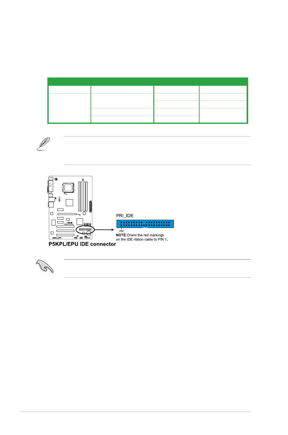
IDE connector (40-1 pin PRI_EIDE)
The onboard IDE connector is for the Ultra DMA 100/66 signal cable. There are three
connectors on each Ultra DMA 100/66 signal cable: blue, black, and gray. Connect the
blue connector to the motherboard’s IDE connector, then select one of the following
modes to configure your device.
Drive jumper setting
Mode of device(s)
Cable connector
Single device
Cable-Select or Master
-
Black
Two devices
Cable-Select
Master
Black
Slave
Gray
Master
Master
Black or gray
Slave
Slave
• Pin 20 on the IDE connector is removed to match the covered hole on the Ultra DMA
cable connector. This prevents incorrect insertion when you connect the IDE cable.
• Use the 80-conductor IDE cable for Ultra DMA 100/66 IDE devices.
If any device jumper is set as “Cable-Select,” ensure that all other device jumpers have the
same setting.
- P5B Premium Vista Edition (188 pages)
- P5B (140 pages)
- P5B (56 pages)
- P5KPL-VM/1394/SI (94 pages)
- M2N68-CM (28 pages)
- P5GD1-VM (92 pages)
- P5AD2-E Premium (2 pages)
- P5GD1-VM (88 pages)
- P5AD2 Premium (8 pages)
- DELUXE A7N8X-E (114 pages)
- P5KPL-AM SE (40 pages)
- P5KPL-AM SE (38 pages)
- P5KPL-AM SE (62 pages)
- P4S8X-X (64 pages)
- P5K-VM (98 pages)
- K8V-X SE (82 pages)
- M2N68-AM SE2 (40 pages)
- P4P800 SE (125 pages)
- P4P800 SE (16 pages)
- DELUXE SERIES M3A32-MVP (176 pages)
- P5AD2 Deluxe (148 pages)
- M4A79 Deluxe (122 pages)
- A7V266-E (108 pages)
- Application Manual (5 pages)
- Application Manual (11 pages)
- Application Manual (10 pages)
- Application Manual (4 pages)
- Application Manual (8 pages)
- Application Manual (2 pages)
- Application Manual (6 pages)
- Application Manual (9 pages)
- Application Manual (3 pages)
- Application Manual (1 page)
- M4A88T-I DELUXE (70 pages)
- M4A88T-I DELUXE (44 pages)
- P9X79 DELUXE (2 pages)
- RAMPAGE IV GENE (1 page)
- P9X79 (156 pages)
- P8H61-M PLUS V3 (64 pages)
- A85XM-A (78 pages)
- M4A78L-M LE (64 pages)
- M2N68-AM (96 pages)
- M2N68-AM (62 pages)
- M2N68-AM (38 pages)
- Blitz Formula (3 pages)