M2n68 se analog front panel connector, Aafp – Asus M2N68 SE User Manual
Page 32
6.
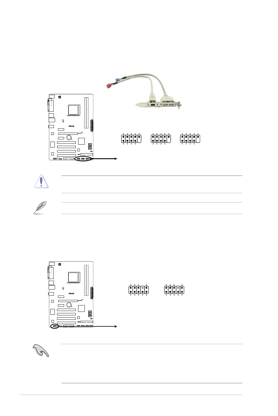
USB connectors (10-1 pin USB56, USB 78, USB910)
These connectors are for USB 2.0 ports. Connect the USB module cable to any of
these connectors, then install the module to a slot opening at the back of the system
chassis. These USB connectors comply with USB 2.0 specification that supports up to
480 Mbps connection speed.
M2N68 SE
M2N68 SE USB2.0 connectors
PIN 1
USB+5
V
USB_P6
-
USB_P6
+
GND
NC
USB+5V
USB_P5
-
USB_P5
+
GND
USB56
USB78
PIN 1
USB+5
V
USB_P8
-
USB_P8
+
GND
NC
USB+5V
USB_P7
-
USB_P7
+
GND
USB910
PIN 1
USB+5
V
USB_P10-
USB_P10+
GND
NC
USB+5V
USB_P9
-
USB_P9
+
GND
Never connect a 1394 cable to the USB connectors. Doing so will damage the
motherboard!
The USB 2.0 module is purchased separately.
7.
Front panel audio connector (10-1 pin AAFP)
This connector is for a chassis-mounted front panel audio I/O module that supports
either High Definition Audio or AC`97 audio standard. Connect one end of the front
panel audio I/O module cable to this connector.
M2N68 SE
M2N68 SE Analog front panel connector
AAFP
PIN 1
GN
D
PRESENCE#
SENSE1_RETUR
SENSE2_RETUR
PORT1
L
PORT1
R
PORT2
R
SENSE_SEND
PORT1
L
HD-audio-compliant
pin definition
PIN 1
AGND
NC
NC
NC
MIC
2
MICPWR
Line out_
R
NC
Line out_L
Legacy AC’97
compliant definition
• We recommend that you connect a high-definition front panel audio module to this
connector to avail of the motherboard high-definition audio capability.
• By default, this connector is set to [HD Audio]. If you want to connect a High Definition
front panel audio module to this connector, set the Front Panel Select item in the BIOS
to [HD Audio]. See section “2.4.3 Chipset” for details.
1-22
ASUS M2N68 SE