Iii. hardware setup, Using the asus cidb, Setting up the asus cidb – Asus MEL User Manual
Page 33: Asus mel user’s manual 33, Connectors iii. h/w setup
ASUS MEL User’s Manual
33
III. HARDWARE SETUP
Using the ASUS CIDB
1. You must have an ASUS motherboard with a chassis connector.
2. Connect the CIDB directly to the chassis connector or use the provided extension
cable and mount the CIDB to the chassis using a double-sided foam adhesive tape.
CAUTION!
The CIDB component pins and metallic points must not come in
contact with another metallic surface or else shorting will occur!
3. Check the hardware settings:
•
JP1 jumper should be enabled to use the photo sensor
•
MS1 and MS2 connectors should be connected to momentary toggle switches
mounted on the chassis to use the contact method for triggering alarms.
•
SW jumper should be enabled to allow the hardware monitoring compo-
nents to receive signals from the CIDB.
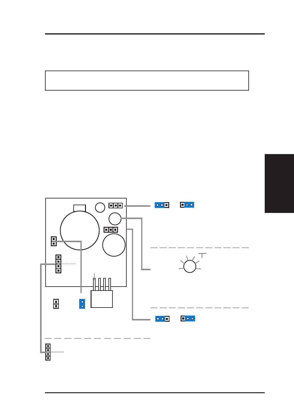
4. To stop the alarm from sounding, use the LDCM software or place a jumper on
(or short manually) the CLR jumper momentarily.
5. If you have an updated BIOS with intrusion support, booting the computer after
an intrusion will require a password which is configured through BIOS.
Normal
Clear
Clear:
Stops the sounding alarm
CLR
CLR
Enable
Disable
JP1:
Enable/Disable
the Photo Sensor
JP1
JP1
1
1
MS1
MS2
MS1/MS2:
Micro Switch from the chassis
panel can be connected here
to trigger the chassis intrusion
alarm.
Enable
Disable
SW:
Enable/Disable chassis intrusion
function in the motherboard
SW
SW
1
1
Setting up the ASUS CIDB
CON:
Sensitivity adjustment for the
photo sensor, (0) is least sensitive
and (5) is most sensitive
CON
1
2
3
4
5
0 (not sensitive)
best range
(sensitive)
CR2032 3V
Lithium Cell
Buzzer
MS1
CLR
JP1
CON
OR
SW
MS2
+5 volt standby
from power supply
Connectors
III. H/W SETUP