Iii. hardware setup – Asus MEL User Manual
Page 17
ASUS MEL User’s Manual
17
III. HARDWARE SETUP
System Memory
III. H/W SETUP
General DIMM Notes
•
Two possible memory chips are supported: SDRAM with and without ECC.
•
SDRAM chips are generally thinner with higher pin density than EDO (Ex-
tended Data Output) chips.
•
BIOS shows SDRAM memory on bootup screen.
•
8 chips/side modules do not support ECC, only 9 chips/side modules support ECC.
•
Single-sided DIMMs come in 16, 32, 64,128MB; double-sided come in 32, 64,
128, 256MB.
2. System Memory (DIMM)
NOTE: No hardware or BIOS setup is required after adding or removing memory.
This motherboard uses only Dual Inline Memory Modules (DIMMs). Sockets are
available for 3.3Volt (power level) unbuffered Synchronous Dynamic Random Ac-
cess Memory (SDRAM) of either 8, 16, 32, 64, 128MB, or 256MB. One side (with
memory chips) of the DIMM takes up one row on the motherboard.
To utilize the chipset’s Error Checking and Correction (ECC) feature, you must use a
DIMM module with 9 chips per side (standard 8 chips/side + 1 parity chip) and make
the proper settings in BIOS Chipset Features Setup of BIOS SETUP.
Memory speed setup is recommended through “SDRAM Configuration” under
Chipset Features Setup in BIOS SETUP.
NOTE: The LX chipset does not support registered DIMMs.
WARNING!
Memory modules must have 18 chips or less. Memory modules with
more than 18 chips exceed specifications and may cause unstable operation.
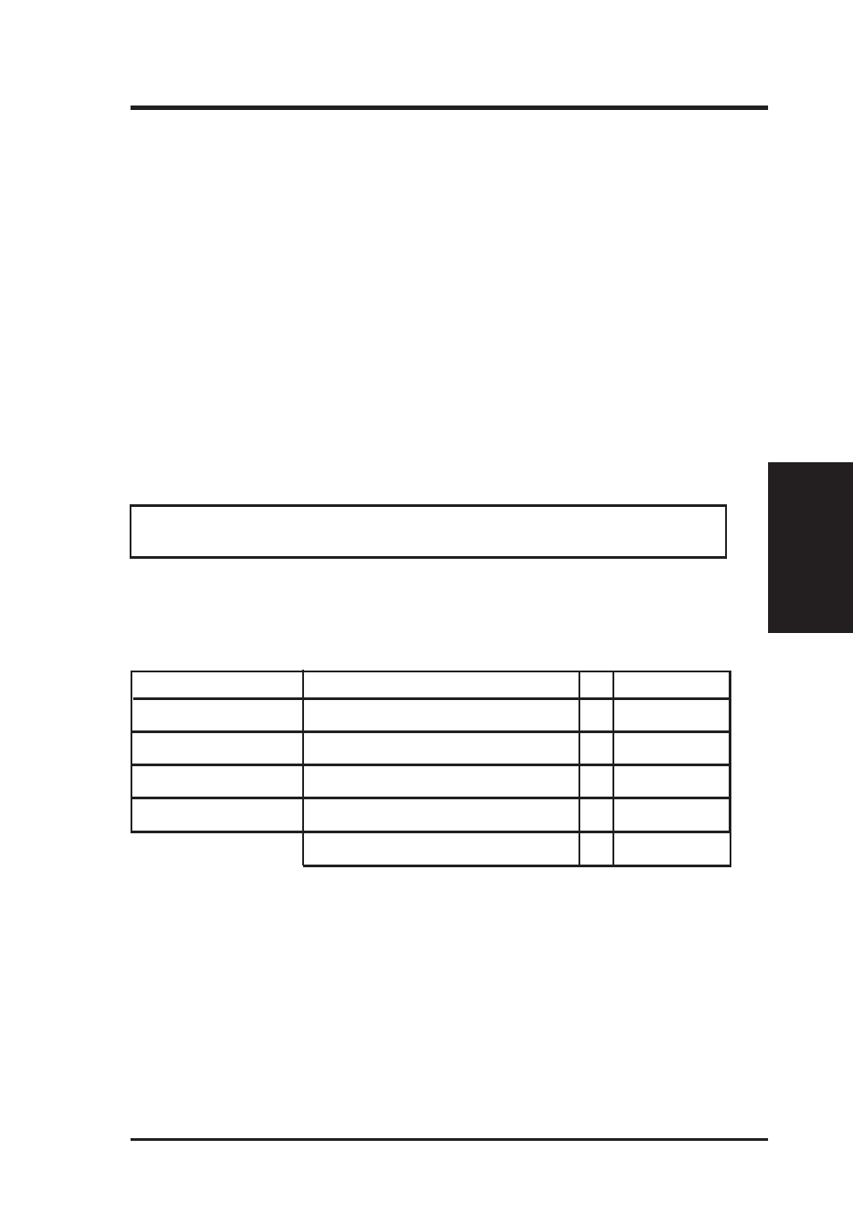
Install memory in any combination as follows:
DIMM Location
168-pin DIMM
Total Memory
Socket 1 (Rows 0&1)
SDRAM 8, 16, 32, 64, 128, 256MB
x1
Socket 2 (Rows 2&3)
SDRAM 8, 16, 32, 64, 128, 256MB
x1
Socket 3 (Rows 4&5)
SDRAM 8, 16, 32, 64, 128, 256MB
x1
Socket 4 (Rows 6&7)
SDRAM 8, 16, 32, 64, 128, 256MB
x1
Total System Memory (Max 1024MB)
=