Asus P5V-X SE User Manual
Page 46
1-34
Chapter 1: Product introduction
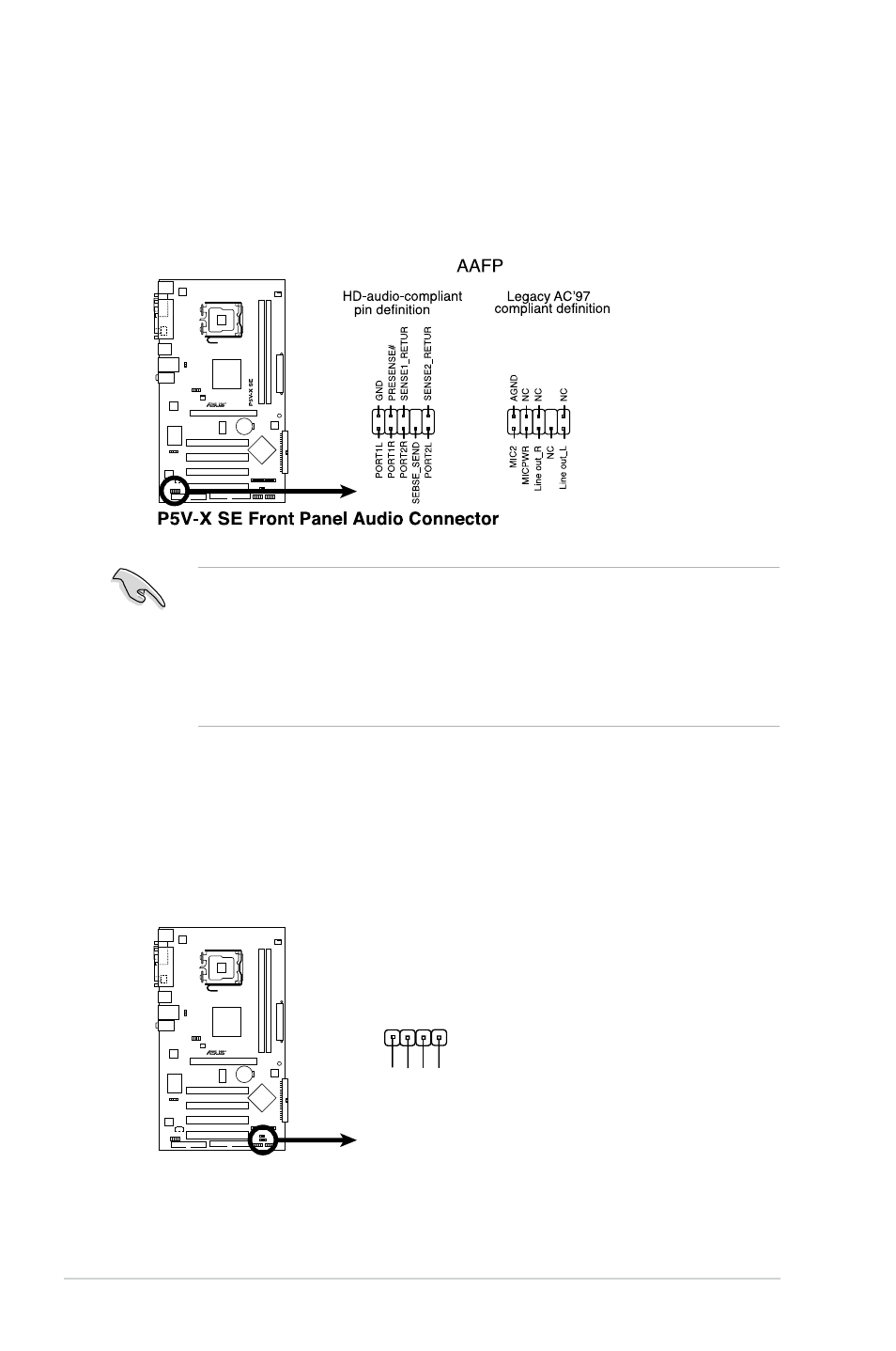
9. Front panel audio connector (10-1 pin AAFP)
This connector is for a chassis-mounted front panel audio I/O module that
supports either High Definition Audio or legacy AC ‘97 audio standard.
Connect one end of the front panel audio I/O module cable to this connector.
• Use a chassis that provides a high-definition audio front panel audio I/O to
use the high-definition audio features.
• By default, this connector is set to [AC97]. If you want to connect a High-
Definition front panel audio module to this connector, set the Front Panel
Support Type item in the BIOS Setup to [HD Audio]. See page 2-22 for
details.
10. Speaker connector (4-pin SPEAKER)
This connector is for the chassis-mounted system warning speaker. The
speaker allows you to hear system beeps and warnings.
P5
V
-X SE
P5V-X SE Speaker Out Connector
SPEAKER
+5V
GND
GND
Speaker Out
1
- P5B Premium Vista Edition (188 pages)
- P5B (140 pages)
- P5B (56 pages)
- P5KPL-VM/1394/SI (94 pages)
- M2N68-CM (28 pages)
- P5GD1-VM (92 pages)
- P5AD2-E Premium (2 pages)
- P5GD1-VM (88 pages)
- P5AD2 Premium (8 pages)
- DELUXE A7N8X-E (114 pages)
- P5KPL-AM SE (40 pages)
- P5KPL-AM SE (38 pages)
- P5KPL-AM SE (62 pages)
- P4S8X-X (64 pages)
- P5K-VM (98 pages)
- K8V-X SE (82 pages)
- M2N68-AM SE2 (40 pages)
- P4P800 SE (125 pages)
- P4P800 SE (16 pages)
- DELUXE SERIES M3A32-MVP (176 pages)
- P5AD2 Deluxe (148 pages)
- M4A79 Deluxe (122 pages)
- A7V266-E (108 pages)
- Application Manual (5 pages)
- Application Manual (11 pages)
- Application Manual (10 pages)
- Application Manual (4 pages)
- Application Manual (8 pages)
- Application Manual (2 pages)
- Application Manual (6 pages)
- Application Manual (9 pages)
- Application Manual (3 pages)
- Application Manual (1 page)
- M4A88T-I DELUXE (70 pages)
- M4A88T-I DELUXE (44 pages)
- P9X79 DELUXE (2 pages)
- RAMPAGE IV GENE (1 page)
- P9X79 (156 pages)
- P8H61-M PLUS V3 (64 pages)
- A85XM-A (78 pages)
- M4A78L-M LE (64 pages)
- M2N68-AM (96 pages)
- M2N68-AM (62 pages)
- M2N68-AM (38 pages)
- Blitz Formula (3 pages)