2 internal connectors, Audio 2, 4, 6, 8-channel configuration – Asus M4A87TD/USB3 User Manual
Page 33
1.12.2
Internal connectors
1.
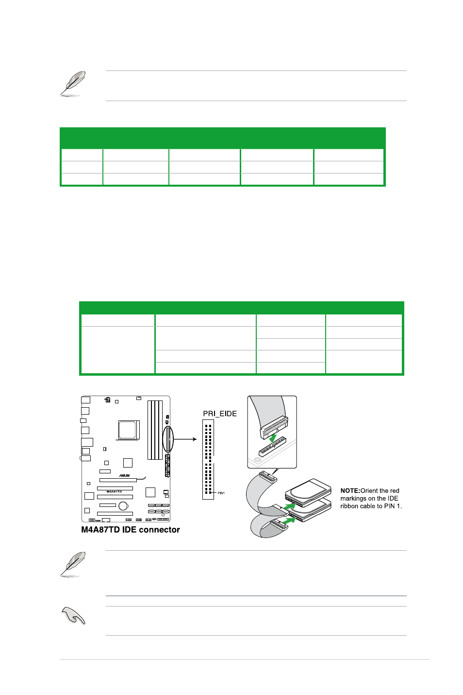
IDE connector (40-1 pin PRI_IDE)
The onboard IDE connector is for Ultra DMA 133/100/66 signal cable. There are three
connectors on each Ultra DMA 133 / 100 / 66 signal cable: blue, black, and gray.
Connect the blue connector to the motherboard’s IDE connector, then select one of the
following modes to configure your devices:
Drive jumper setting
Mode of device(s)
Cable connector
Single device
Cable-Select or Master
-
Black
Two devices
Cable-Select
Master
Black
Slave
Gray
Master
Master
Black or gray
Slave
Slave
• Pin 20 on the IDE connector is removed to match the covered hole on the Ultra DMA
cable connector. This prevents incorrect insertion when you connect the IDE cable.
• Use the 80-conductor IDE cable for Ultra DMA 133/100/66 IDE devices.
If any device jumper is set as “Cable-Select”, ensure that all other device jumpers have the
same setting.
Refer to the audio configuration table below for the function of the audio ports in
2, 4, 6, or 8-channel configuration.
Audio 2, 4, 6, 8-channel configuration
Port
Headset
2-channel
4-channel
6-channel
8-channel*
Light Blue
Line In
Rear Speaker Out
Rear Speaker Out
Rear Speaker Out
Lime
Line Out
Front Speaker Out
Front Speaker Out
Front Speaker Out
Pink
Mic In
Mic In
Center/Subwoofer
Center/Subwoofer
*When setting up to the 8-channel configuration, use either one of the front panel audio connectors as Side Speaker
Out.
Chapter 1: Product introduction
1-21