Asus A8V-E SE User Manual
Page 41
A S U S A 8 V - E S E
A S U S A 8 V - E S E
A S U S A 8 V - E S E
A S U S A 8 V - E S E
A S U S A 8 V - E S E
1 - 2 9
1 - 2 9
1 - 2 9
1 - 2 9
1 - 2 9
1 0 .
1 0 .
1 0 .
1 0 .
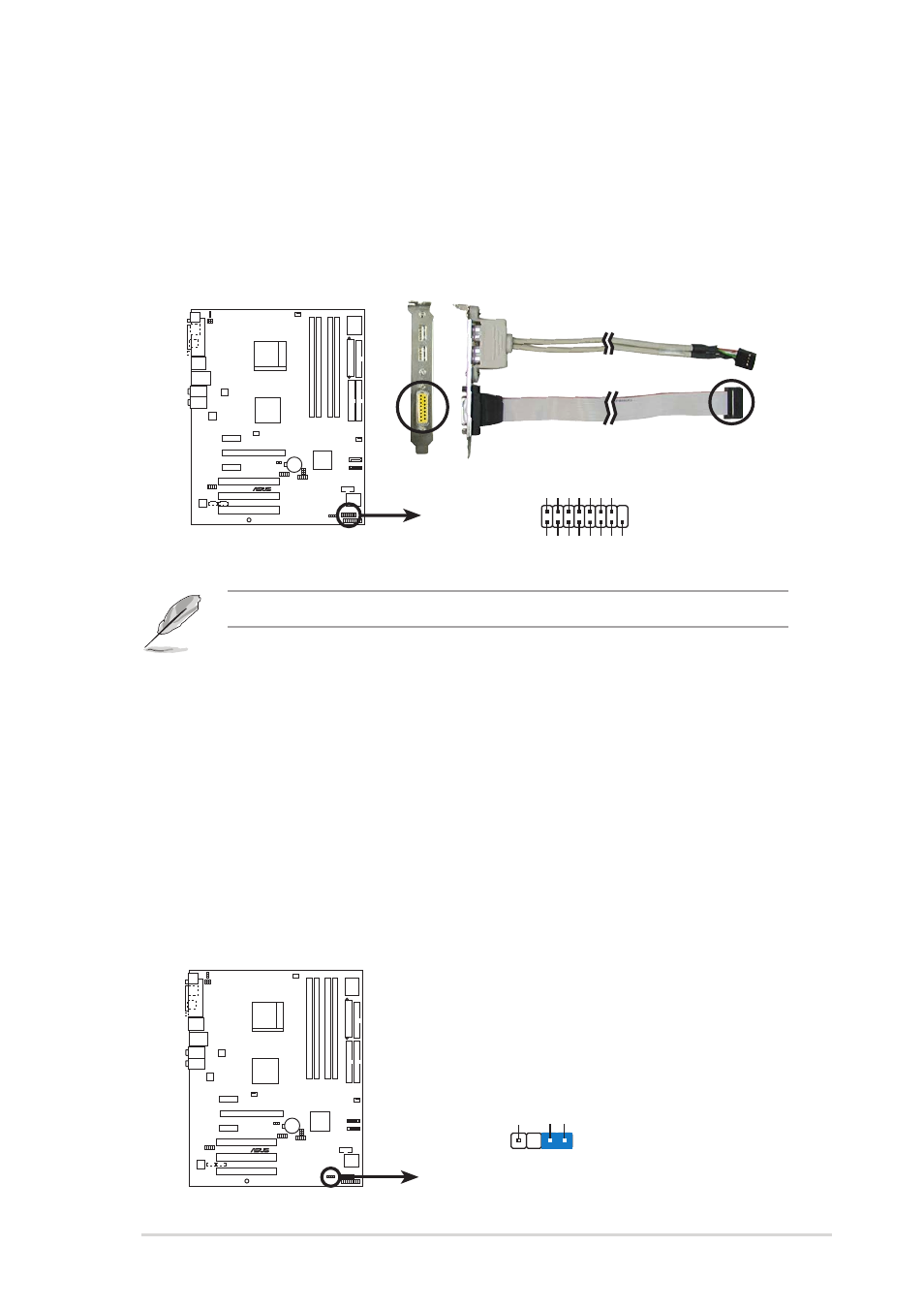
1 0 . GAME/MIDI port connector (16-1 pin GAME)
G A M E / M I D I p o r t c o n n e c t o r ( 1 6 - 1 p i n G A M E )
G A M E / M I D I p o r t c o n n e c t o r ( 1 6 - 1 p i n G A M E )
G A M E / M I D I p o r t c o n n e c t o r ( 1 6 - 1 p i n G A M E )
G A M E / M I D I p o r t c o n n e c t o r ( 1 6 - 1 p i n G A M E )
This connector is for a GAME/MIDI port. Connect the USB/GAME
module cable to this connector, then install the module to a slot
opening at the back of the system chassis. The GAME/MIDI port
connects a joystick or game pad for playing games, and MIDI devices
for playing or editing audio files.
A8V-E SE
®
A8V-E SE Game connector
GAME
+5V
+5V
J2B1
J2CX
MIDI_OUT
J2CY
J2B2
MIDI_IN
J1B1
J1CX
GND
GND
J1CY
J1B2
+5V
The USB/GAME port module is purchased separately.
1 1 .
1 1 .
1 1 .
1 1 .
1 1 . Chassis intrusion connector (4-1 pin CHASSIS)
C h a s s i s i n t r u s i o n c o n n e c t o r ( 4 - 1 p i n C H A S S I S )
C h a s s i s i n t r u s i o n c o n n e c t o r ( 4 - 1 p i n C H A S S I S )
C h a s s i s i n t r u s i o n c o n n e c t o r ( 4 - 1 p i n C H A S S I S )
C h a s s i s i n t r u s i o n c o n n e c t o r ( 4 - 1 p i n C H A S S I S )
This connector is for a chassis-mounted intrusion detection sensor or
switch. Connect one end of the chassis intrusion sensor or switch
cable to this connector. The chassis intrusion sensor or switch sends a
high-level signal to this connector when a chassis component is
removed or replaced. The signal is then generated as a chassis
intrusion event.
By default, the pins labeled “Chassis Signal” and “Ground” are shorted
with a jumper cap. Remove the jumper caps only when you intend to
use the chassis intrusion detection feature.
A8V-E SE
®
A8V-E SE Chassis alarm lead
CHASSIS
+5VSB_MB
Chassis Signal
GND
(Default)