Asus P5P800-MX User Manual
Page 41
A S U S P 5 P 8 0 0 - M X
A S U S P 5 P 8 0 0 - M X
A S U S P 5 P 8 0 0 - M X
A S U S P 5 P 8 0 0 - M X
A S U S P 5 P 8 0 0 - M X
1 - 2 9
1 - 2 9
1 - 2 9
1 - 2 9
1 - 2 9
9 .
9 .
9 .
9 .
9 .
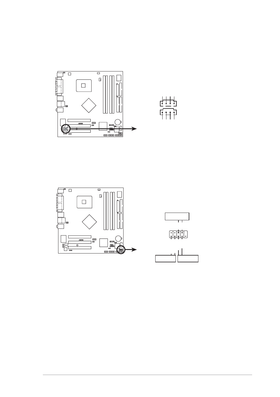
I n t e r n a l a u d i o c o n n e c t o r s ( 4 - p i n C D 1 , A U X 1 )
I n t e r n a l a u d i o c o n n e c t o r s ( 4 - p i n C D 1 , A U X 1 )
I n t e r n a l a u d i o c o n n e c t o r s ( 4 - p i n C D 1 , A U X 1 )
I n t e r n a l a u d i o c o n n e c t o r s ( 4 - p i n C D 1 , A U X 1 )
I n t e r n a l a u d i o c o n n e c t o r s ( 4 - p i n C D 1 , A U X 1 )
These connectors allow you to receive stereo audio input from sound
sources such as a CD-ROM, TV tuner, MPEG card or modem.
P5P800-MX
®
P5P800-MX Internal audio connectors
CD1(Black)
AUX1(White)
Right A
udio Channel
Left A
udio Channel
Ground
Ground
Right A
udio Channel
Left A
udio Channel
Ground
Ground
P5P800-MX
®
P5P800-MX System panel connector
F_PANEL1
PWR
Ground
GND
Reset
IDE_LED+
IDE_LED-
RESET
IDE LED
PWRSW
1 0 .
1 0 .
1 0 .
1 0 .
1 0 . System Front panel connectors (10-pin F_PANEL1)
S y s t e m F r o n t p a n e l c o n n e c t o r s ( 1 0 - p i n F _ P A N E L 1 )
S y s t e m F r o n t p a n e l c o n n e c t o r s ( 1 0 - p i n F _ P A N E L 1 )
S y s t e m F r o n t p a n e l c o n n e c t o r s ( 1 0 - p i n F _ P A N E L 1 )
S y s t e m F r o n t p a n e l c o n n e c t o r s ( 1 0 - p i n F _ P A N E L 1 )
This connector supports several chassis-mounted functions.
•
P o w e r / S o f t - o f f b u t t o n ( 2 - p i n P W R S W )
P o w e r / S o f t - o f f b u t t o n ( 2 - p i n P W R S W )
P o w e r / S o f t - o f f b u t t o n ( 2 - p i n P W R S W )
P o w e r / S o f t - o f f b u t t o n ( 2 - p i n P W R S W )
P o w e r / S o f t - o f f b u t t o n ( 2 - p i n P W R S W )
This connector is for the system power button. Pressing the power
button turns the system ON or puts the system in SLEEP or SOFT-OFF
mode depending on the BIOS settings. Pressing the power switch for
more than four seconds while the system is ON turns the system OFF.
•
H a r d d i s k d r i v e a c t i v i t y ( 2 - p i n I D E _ L E D )
H a r d d i s k d r i v e a c t i v i t y ( 2 - p i n I D E _ L E D )
H a r d d i s k d r i v e a c t i v i t y ( 2 - p i n I D E _ L E D )
H a r d d i s k d r i v e a c t i v i t y ( 2 - p i n I D E _ L E D )
H a r d d i s k d r i v e a c t i v i t y ( 2 - p i n I D E _ L E D )
This 2-pin connector is for the HDD Activity LED. Connect the HDD
Activity LED cable to this connector. The IDE LED lights up or flashes
when data is read from or written to the HDD.
•
R e s e t b u t t o n ( 2 - p i n R E S E T )
R e s e t b u t t o n ( 2 - p i n R E S E T )
R e s e t b u t t o n ( 2 - p i n R E S E T )
R e s e t b u t t o n ( 2 - p i n R E S E T )
R e s e t b u t t o n ( 2 - p i n R E S E T )
This 2-pin connector is for the chassis-mounted reset button for
system reboot without turning off the system power.