Hardware setup – Asus CUW-B User Manual
Page 42
42
ASUS CUW-B User’s Manual
Connectors
3. H/W SETUP
3. HARDWARE SETUP
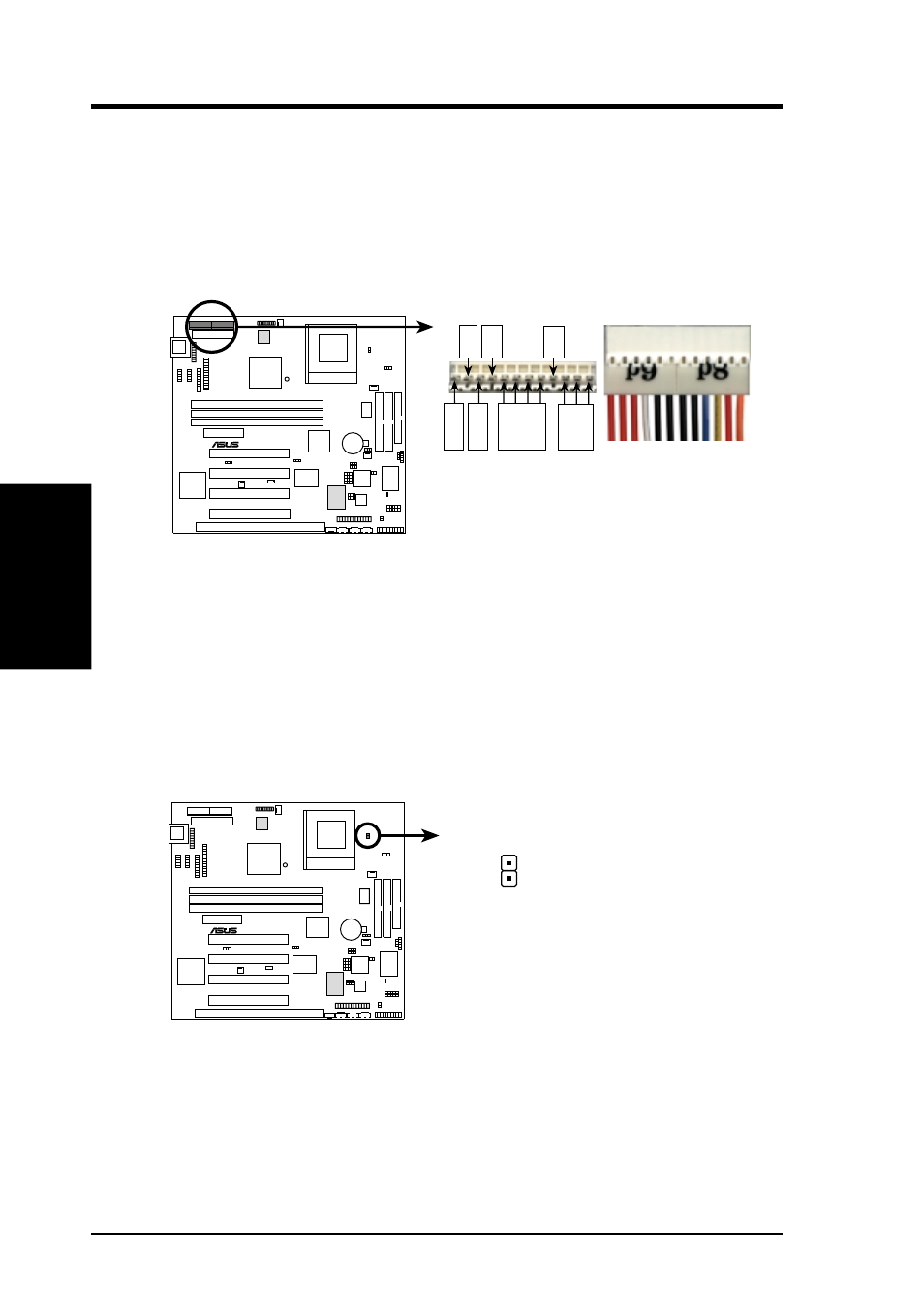
29) AT Power Supply Connector (12-pin block PS2)
This connector connects to a standard 5 Volt power supply. To connect the
leads from the power supply, ensure first that the power supply is not plugged.
Most power supplies provide two plugs (P8 and P9), each containing six wires,
two of which are black. Orient the connectors so that the black wires are to-
gether.
0
1
®
CUW-B
CUW-B AT Power Connector
Power Plugs from
Power Supply
Power Connector
on Motherboard
P8
P9
RED
RED
RED
WHT
BLK
BLK
BLK
BLK
BLU
YL
W
RED
ORG
+5V
PG
+12V
GND
+5V
-12V
-5V
At a slight angle, align the plastic guide pins on the lead to their receptacles on
the connector. Once aligned, press the lead onto the connector until the lead
locks into place.
30) Thermal Sensor Connector (2-pin JTPWR)
If you have a power supply with thermal monitoring, connect its thermal sensor
cable to this connector.
0
1
®
CUW-B
CUW-B Thermal Sensor Connector
JTPWR
Power Supply Thermal Sensor
- P5B (56 pages)
- P5B Premium Vista Edition (188 pages)
- P5B (140 pages)
- P5KPL-VM/1394/SI (94 pages)
- M2N68-CM (28 pages)
- P5AD2 Premium (8 pages)
- P5GD1-VM (92 pages)
- P5AD2-E Premium (2 pages)
- P5GD1-VM (88 pages)
- DELUXE A7N8X-E (114 pages)
- P5KPL-AM SE (40 pages)
- P5KPL-AM SE (38 pages)
- P5KPL-AM SE (62 pages)
- P4S8X-X (64 pages)
- P5K-VM (98 pages)
- K8V-X SE (82 pages)
- M2N68-AM SE2 (40 pages)
- P4P800 SE (125 pages)
- P4P800 SE (16 pages)
- DELUXE SERIES M3A32-MVP (176 pages)
- P5AD2 Deluxe (148 pages)
- M4A79 Deluxe (122 pages)
- A7V266-E (108 pages)
- Application Manual (3 pages)
- Application Manual (1 page)
- Application Manual (5 pages)
- Application Manual (11 pages)
- Application Manual (10 pages)
- Application Manual (4 pages)
- Application Manual (8 pages)
- Application Manual (2 pages)
- Application Manual (6 pages)
- Application Manual (9 pages)
- M4A88T-I DELUXE (70 pages)
- M4A88T-I DELUXE (44 pages)
- P9X79 (156 pages)
- P9X79 DELUXE (2 pages)
- RAMPAGE IV GENE (1 page)
- P8H61-M PLUS V3 (64 pages)
- A85XM-A (78 pages)
- M4A78L-M LE (64 pages)
- M2N68-AM (96 pages)
- M2N68-AM (62 pages)
- M2N68-AM (38 pages)
- Blitz Extreme (188 pages)