Iii. installation, Asus p2l-b user’s manual 31 – Asus P2L-B User Manual
Page 31
ASUS P2L-B User’s Manual
31
III. INSTALLATION
(Connectors)
III. INST
ALLA
TION
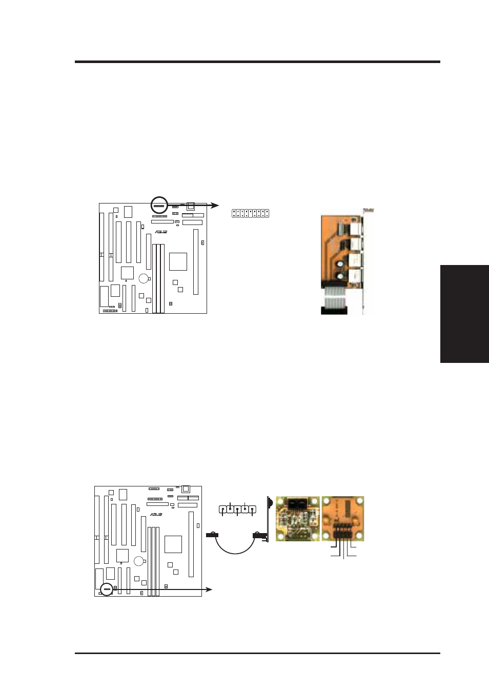
16. USB, Infrared, PS/2 Mouse Module Connector (USB/MIR, 18-1 pins)
If you want to use USB, PS/2 mouse, or infrared (IrDA) devices, you need to
purchase an external connector set. The external connector set connects to the
18-pin block and mounts to an open slot on your computer’s chassis. The system
will direct IRQ12 to the PS/2 mouse if one is detected. If not detected, expan-
sion cards can use IRQ12. See PS/2 Mouse Control in BIOS Features Setup
and USB Function in PnP and PCI Setup of the BIOS SOFTWARE. See Sec-
ond IrDA... connector for details on the infrared connector.
PS/2
Mouse
Infrared
USB 0
USB 1
1: USB +5 Volt
2: USB Port 0 -
3: USB Port 0 +
4: Ground
5: (no connection)
6: PS/2 Mouse Clock
7: Ground
8: (no connection)
9: +5 Volt
P2L-B PS/2 Mouse, USB, IrDA Module Connector
10: USB +5 Volt
11: USB Port 1 -
12: USB Port 1 +
13: Ground
14: (no connection)
15: PS/2 Mouse Data
16: Ground
17: Infrared Receive
18: Infrared Transmit
Optional USB/MIR
R
1
9
18
10
17. Second IrDA-Compliant Infrared Connector (IR, 5-pins)
This connector supports the optional wireless transmitting and receiving infra-
red module. This module mounts to a small opening on system cases that sup-
port this feature. You must also configure the setting through UART2 Use Infra-
red in Chipset Features Setup to select whether UART2 is directed for use
with COM2 or IrDA. Use the five pins as shown below (Back View) and con-
nect a ribbon cable from the module to the motherboard according to the pin
definitions.
R
Front View
+5V
IRTX
IRRX
(NC)
GND
Back View
P2L-B Infrared Module Connector
+5V
IRRX
IR
TX
(NC)
GND