Hardware setup, Asus cuv4x-me user’s manual 35 – Asus CUV4X-ME User Manual
Page 35
ASUS CUV4X-ME User’s Manual
35
3. HARDWARE SETUP
Connectors
3. H/W SETUP
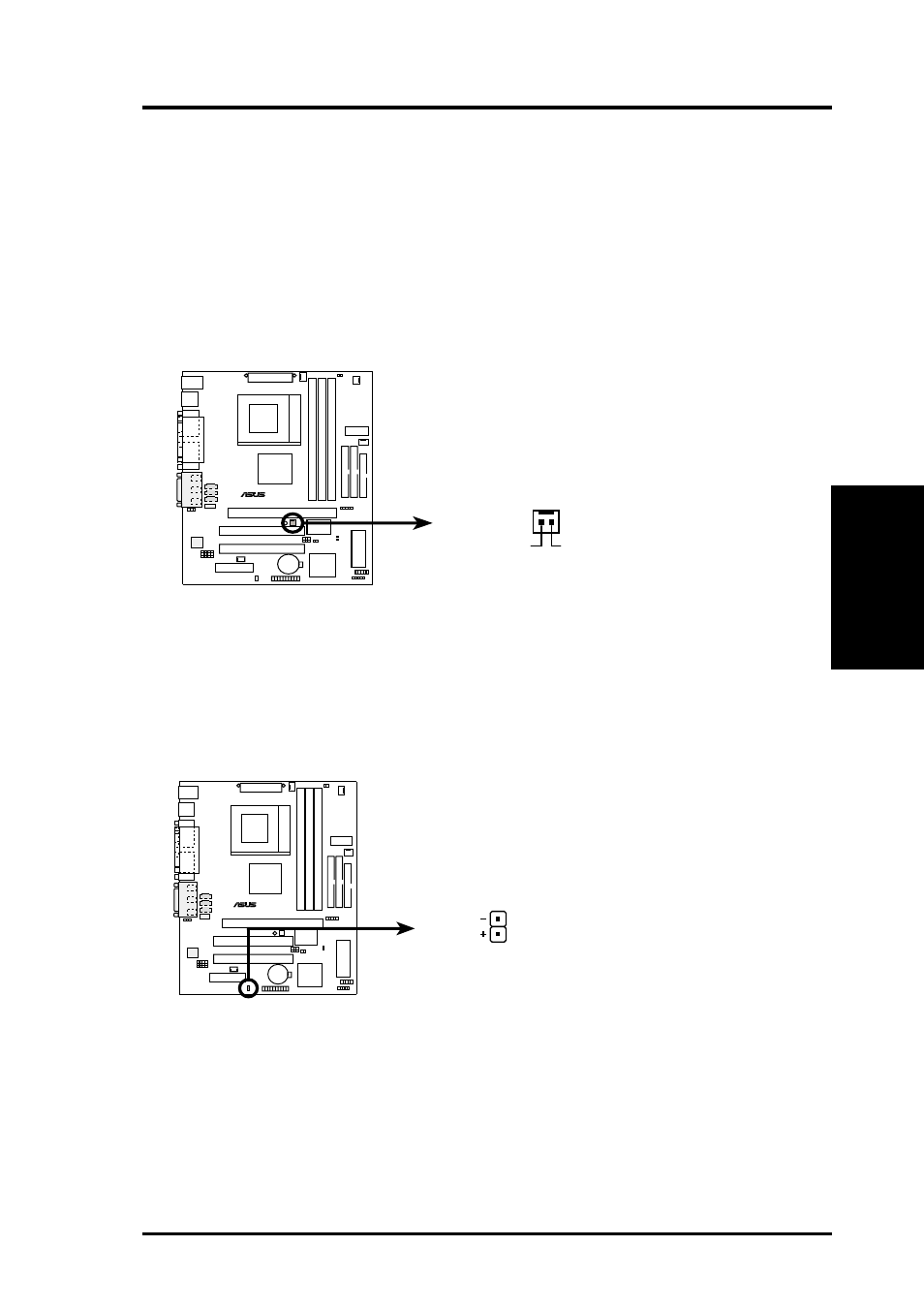
12) Wake-On-Ring Connector (2-pin WOR)
This connector connects to internal modem cards with a Wake-On-Ring output.
The connector powers up the system when a ringup packet or signal is received
through the internal modem card. NOTE: For external modems, Wake-On-Ring
is detected through the COM port.
IMPORTANT: This feature requires that Wake-On-Ring features are enabled
(see 4.4.3 Power Management) and that your system has an ATX power supply
with at least 720mA +5V standby power.
CUV4X-ME Wake-On-Ring Connector
®
CUV4X-ME
WOR
RI#
Ground
2
1
13) IDE Activity LED (2-pin IDELED)
This connector supplies power to the cabinet’s IDE activity LED. Read and
write activity by devices connected to the Primary or Secondary IDE connectors
will cause the LED to light up.
CUV4X-ME IDE Activity LED
TIP: If the case-mounted LED does not
light, try reversing the 2-pin plug.
IDELED
®
CUV4X-ME
- P5B (56 pages)
- P5B Premium Vista Edition (188 pages)
- P5B (140 pages)
- P5KPL-VM/1394/SI (94 pages)
- M2N68-CM (28 pages)
- P5AD2 Premium (8 pages)
- P5GD1-VM (92 pages)
- P5AD2-E Premium (2 pages)
- P5GD1-VM (88 pages)
- DELUXE A7N8X-E (114 pages)
- P5KPL-AM SE (40 pages)
- P5KPL-AM SE (38 pages)
- P5KPL-AM SE (62 pages)
- P4S8X-X (64 pages)
- P5K-VM (98 pages)
- K8V-X SE (82 pages)
- M2N68-AM SE2 (40 pages)
- P4P800 SE (125 pages)
- P4P800 SE (16 pages)
- DELUXE SERIES M3A32-MVP (176 pages)
- P5AD2 Deluxe (148 pages)
- M4A79 Deluxe (122 pages)
- A7V266-E (108 pages)
- Application Manual (9 pages)
- Application Manual (3 pages)
- Application Manual (1 page)
- Application Manual (5 pages)
- Application Manual (11 pages)
- Application Manual (10 pages)
- Application Manual (4 pages)
- Application Manual (8 pages)
- Application Manual (2 pages)
- Application Manual (6 pages)
- M4A88T-I DELUXE (70 pages)
- M4A88T-I DELUXE (44 pages)
- P9X79 (156 pages)
- P9X79 DELUXE (2 pages)
- RAMPAGE IV GENE (1 page)
- P8H61-M PLUS V3 (64 pages)
- A85XM-A (78 pages)
- M4A78L-M LE (64 pages)
- M2N68-AM (38 pages)
- M2N68-AM (96 pages)
- M2N68-AM (62 pages)
- Blitz Extreme (188 pages)