2 internal connectors, Internal connectors -19, Internal connectors – Asus M3N78-AM User Manual
Page 29
7.
USB 2.0 ports 1 and 2. These two 4-pin Universal Serial Bus (USB) ports are
available for connecting USB 2.0 devices.
8.
USB 2.0 ports 3 and 4. These two 4-pin Universal Serial Bus (USB) ports are
available for connecting USB 2.0 devices.
9.
Video Graphics Adapter (VGA) port. This 15-pin port is for a VGA monitor or other
VGA-compatible devices.
10. Serial port. This 9-pin COM1 port is for printing devices or other serial devices.
11. USB 2.0 ports 5 and 6. These two 4-pin Universal Serial Bus (USB) ports are
available for connecting USB 2.0 devices.
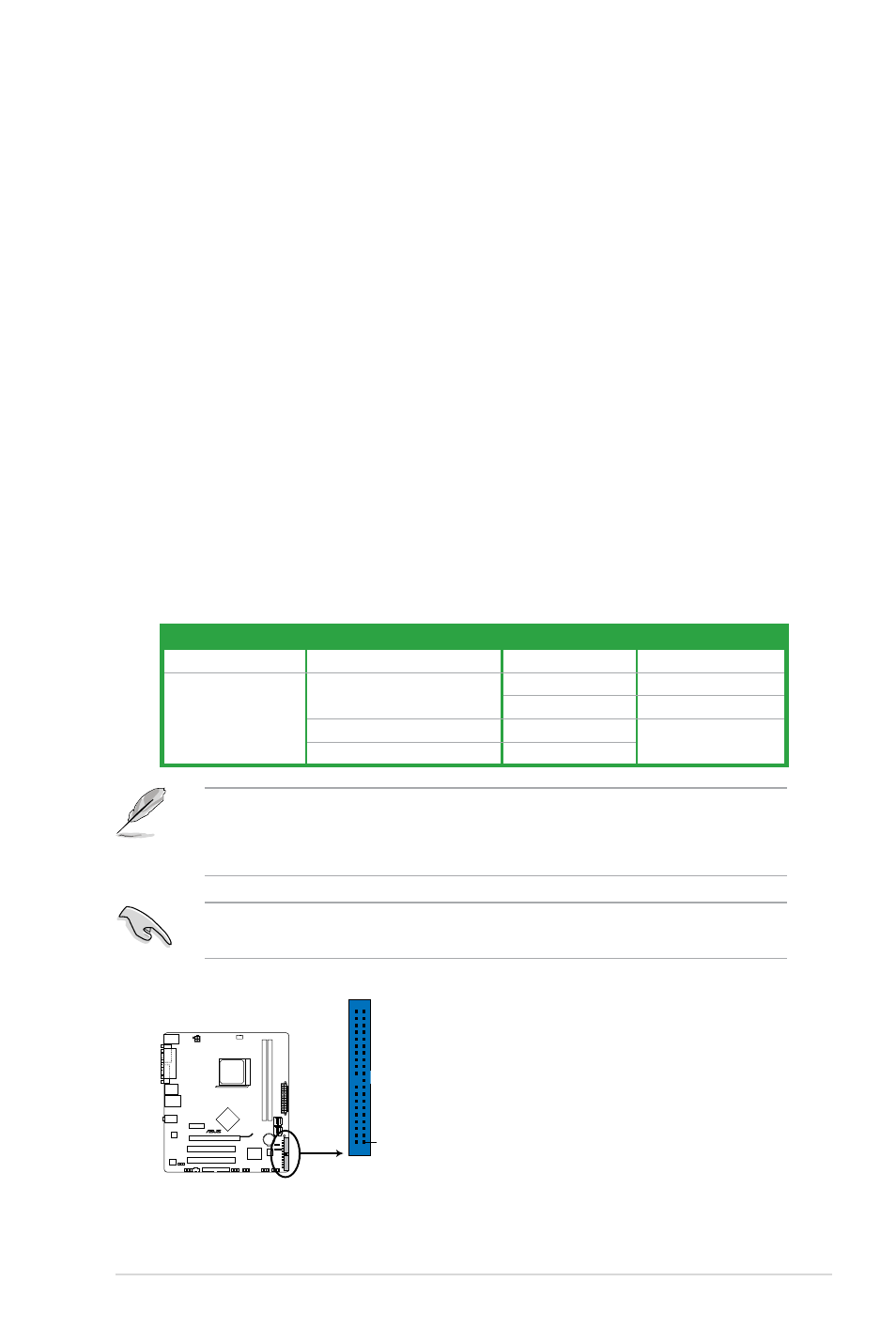
1.
IDE connector (40-1 pin PRI_IDE)
The onboard IDE connector is for an Ultra DMA 133/100/66 signal cable. There are
three connectors on each Ultra DMA 133/100/66 signal cable: blue, black, and gray.
Connect the blue connector to the motherboard’s IDE connector, then select one of the
following modes to configure your device(s).
• Pin 20 on the IDE connector is removed to match the covered hole on the Ultra DMA
cable connector. This prevents incorrect insertion when you connect the IDE cable.
• Use the 80-conductor IDE cable for Ultra DMA 133/100/66 IDE devices.
If any device jumper is set as “Cable-Select,” make sure all other device jumpers have the
same setting.
Drive jumper setting
Mode of device(s)
Cable connector
Single device
Cable-Select or Master
-
Black
Two devices
Cable-Select
Master
Black
Slave
Gray
Master
Master
Black or gray
Slave
Slave
PRI_IDE
NOTE:Orient the red markings
on the IDE ribbon cable to PIN 1.
PIN1
M3N78-AM
M3N78-AM IDE connector
1.10.2
Internal connectors
Chapter 1: Product introduction
1-19