2 motherboard connectors, 3 uaex connectors, Asus terminator barebone system 29 – Asus Terminator Tualatin User Manual
Page 29
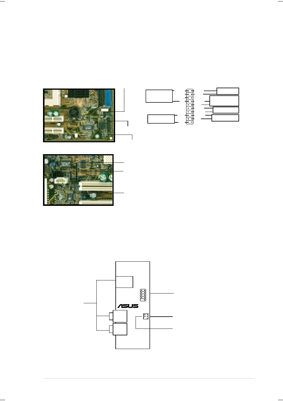
ASUS Terminator Barebone System
29
2.9.2
Motherboard Connectors
The figures below show the specific connectors on the motherboard
where the front panel cables must be connected. You must re-connect
these cables before replacing the chassis cover.
®
USB2P
MIC2
USB
T: Port0
B: Port1
MIC
LOUT
LO2
UAEX
2.9.3
UAEX Connectors
FLOUT Lead (for Line Out Cable)
MIC2 Lead (for Microphone Cable)
Pin 1
PANEL Connector
USB1 Connector
*
Requires an ATX power supply.
PLED
Ground
TB_LED
PWR
+5 V
+5V
Speaker
Ground
+5 V
ExtSMI#
Ground
Reset
Ground
Ground
Power LED
Speaker
Connector
Message LED
SMI Lead
Reset SW
ATX Power
Switch*
IDELED Lead
Front Panel
Connectors
Connect to USB1 Connector
on the Motherboard
Connect to FLOUT Lead
on the Motherboard
Connect to MIC2 Lead
on the Motherboard
See also other documents in the category Asus Computers:
- CG8565 (410 pages)
- CG8565 (246 pages)
- CS5111 (26 pages)
- CS5120 (1 page)
- ET1611PUK (38 pages)
- S2-P8H61E (80 pages)
- P2-PH1 (80 pages)
- P1-P5945G (80 pages)
- P2-P5945GCX (90 pages)
- CG8270 (218 pages)
- CG8270 (536 pages)
- CG8270 (72 pages)
- CG8270 (76 pages)
- CG8270 (534 pages)
- CG8270 (362 pages)
- P3-PH4 (80 pages)
- P3-P5G31 (100 pages)
- P2-M2A690G (80 pages)
- P2-M2A690G (8 pages)
- P4-P5N9300 (1 page)
- P4-P5N9300 (82 pages)
- P1-P5945GC (92 pages)
- P2-P5945GC (92 pages)
- P3-P5G33 (98 pages)
- T3-P5945GC (80 pages)
- T3-P5945GCX (80 pages)
- P2-M2A690G (94 pages)
- T3-PH1 (80 pages)
- T3-PH1 (82 pages)
- T5-P5G41E (82 pages)
- T5-P5G41E (76 pages)
- S1-AT5NM10E (68 pages)
- P6-P7H55E (67 pages)
- ES5000 (174 pages)
- T4-P5G43 (104 pages)
- T-P5G31 (92 pages)
- BT6130 (60 pages)
- BT6130 (54 pages)
- BT6130 (2 pages)
- CG8265 (350 pages)
- CG8265 (210 pages)
- CM1740 (330 pages)
- CM1740 (70 pages)
- CM1740 (198 pages)
- P6-M4A3000E (59 pages)