9 re-connect cables, 1 front panel cables – Asus Terminator Tualatin User Manual
Page 28
28
Chapter 2: Basic Installation
2.9
Re-connect Cables
You may have disconnected some cables when you were installing
components. You must re-connect these cables before you replace
the chassis cover.
2.9.1
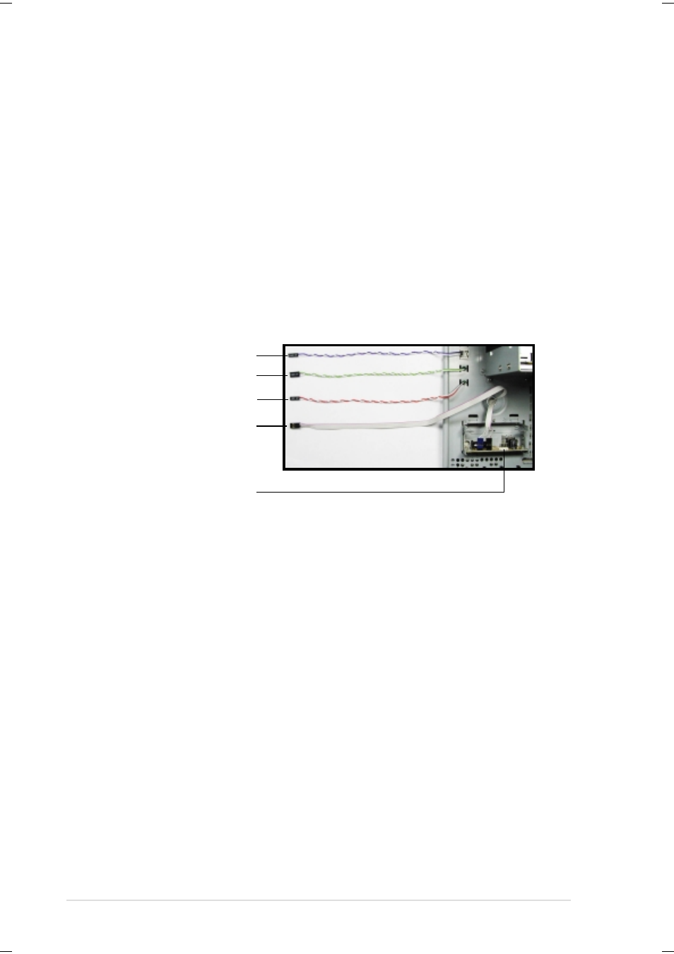
Front Panel Cables
1. Connect the power switch and power LED cables to their
respective leads in the PANEL connector on the motherboard.
2. Connect the HDD LED cable to the 2-pin lead marked IDELED.
3. Connect the Headphone/Mic cable to the FLOUT/MIC2 connector
on the motherboard, matching the red pin stripe with Pin 1.
4. Connect the USB2P cable to the USB1 connector on the
motherboard, matching the red pin stripe with Pin 1.
Power Switch
Power LED
HDD LED
Headphone / Mic
USB Connector (USB2P)
The figure below shows the front panel cables with corresponding
instructions on where to connect them.
- CG8565 (410 pages)
- CG8565 (246 pages)
- CS5111 (26 pages)
- CS5120 (1 page)
- ET1611PUK (38 pages)
- S2-P8H61E (80 pages)
- P1-P5945G (80 pages)
- P2-P5945GCX (90 pages)
- P2-PH1 (80 pages)
- CG8270 (76 pages)
- CG8270 (534 pages)
- CG8270 (362 pages)
- CG8270 (218 pages)
- CG8270 (536 pages)
- CG8270 (72 pages)
- P3-P5G31 (100 pages)
- P3-PH4 (80 pages)
- P2-M2A690G (8 pages)
- P2-M2A690G (80 pages)
- P4-P5N9300 (82 pages)
- P4-P5N9300 (1 page)
- P2-P5945GC (92 pages)
- P1-P5945GC (92 pages)
- P3-P5G33 (98 pages)
- T3-P5945GCX (80 pages)
- T3-P5945GC (80 pages)
- P2-M2A690G (94 pages)
- T3-PH1 (80 pages)
- T3-PH1 (82 pages)
- T5-P5G41E (76 pages)
- T5-P5G41E (82 pages)
- S1-AT5NM10E (68 pages)
- P6-P7H55E (67 pages)
- ES5000 (174 pages)
- T4-P5G43 (104 pages)
- T-P5G31 (92 pages)
- BT6130 (60 pages)
- BT6130 (54 pages)
- BT6130 (2 pages)
- CG8265 (350 pages)
- CG8265 (210 pages)
- CM1740 (330 pages)
- CM1740 (70 pages)
- CM1740 (198 pages)
- P6-M4A3000E (59 pages)