9 re-connect cables, 1 led cables – Asus Terminator P4 533 User Manual
Page 29
ASUS Terminator P4 533 Barebone System
29
2.9
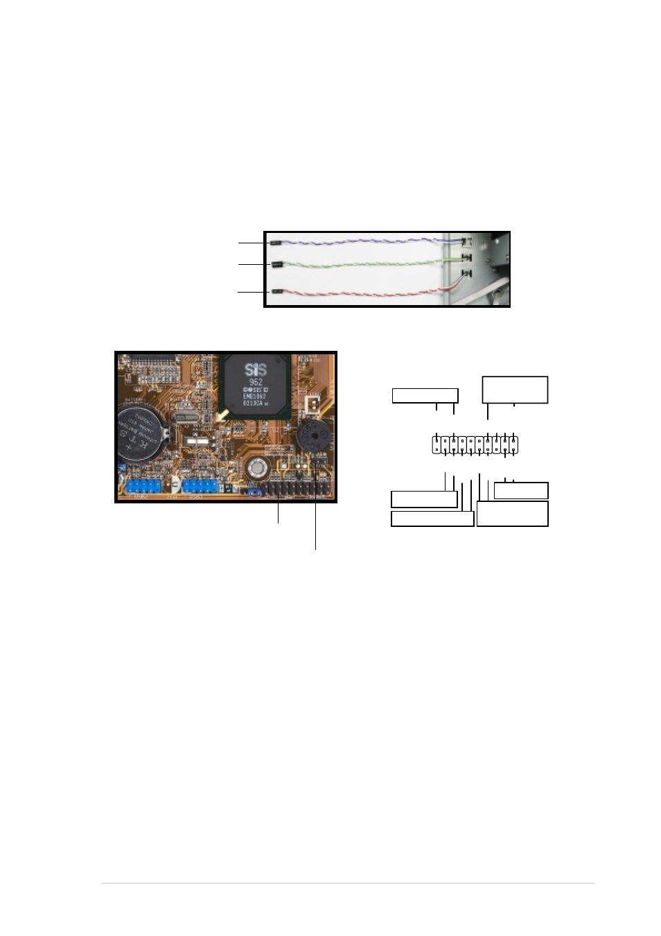
Re-connect cables
You may have disconnected some cables when you were installing
components. You must re-connect these cables before you replace the
chassis cover.
2.9.1
LED cables
•
Connect the power switch and power LED cables to their respective
leads in the PANEL1 connector on the motherboard.
•
Connect the HDD LED cable to the 2-pin lead marked IDE_LED1.
Power Switch
Power LED
HDD LED
PANEL1
IDE_LED1
*
Requires an ATX power supply.
PLED
Ground
MLED
PWR
+5VSB
+5V
Speaker
Speaker
Connector
Power LED
Ground
+5 V
Reset SW
SMI Lead
Message LED
ExtSMI#
Ground
Reset
Ground
Ground
ATX Power
Switch*
PANEL1 Connector
See also other documents in the category Asus Computers:
- CG8565 (410 pages)
- CG8565 (246 pages)
- CS5111 (26 pages)
- CS5120 (1 page)
- ET1611PUK (38 pages)
- S2-P8H61E (80 pages)
- P2-PH1 (80 pages)
- P1-P5945G (80 pages)
- P2-P5945GCX (90 pages)
- CG8270 (218 pages)
- CG8270 (536 pages)
- CG8270 (72 pages)
- CG8270 (76 pages)
- CG8270 (534 pages)
- CG8270 (362 pages)
- P3-PH4 (80 pages)
- P3-P5G31 (100 pages)
- P2-M2A690G (80 pages)
- P2-M2A690G (8 pages)
- P4-P5N9300 (1 page)
- P4-P5N9300 (82 pages)
- P1-P5945GC (92 pages)
- P2-P5945GC (92 pages)
- P3-P5G33 (98 pages)
- T3-P5945GC (80 pages)
- T3-P5945GCX (80 pages)
- P2-M2A690G (94 pages)
- T3-PH1 (80 pages)
- T3-PH1 (82 pages)
- T5-P5G41E (82 pages)
- T5-P5G41E (76 pages)
- S1-AT5NM10E (68 pages)
- P6-P7H55E (67 pages)
- ES5000 (174 pages)
- T4-P5G43 (104 pages)
- T-P5G31 (92 pages)
- BT6130 (60 pages)
- BT6130 (54 pages)
- BT6130 (2 pages)
- CG8265 (350 pages)
- CG8265 (210 pages)
- CM1740 (330 pages)
- CM1740 (70 pages)
- CM1740 (198 pages)
- P6-M4A3000E (59 pages)