Asus Terminator P4 533 User Manual
Page 27
ASUS Terminator P4 533 Barebone System
27
5.
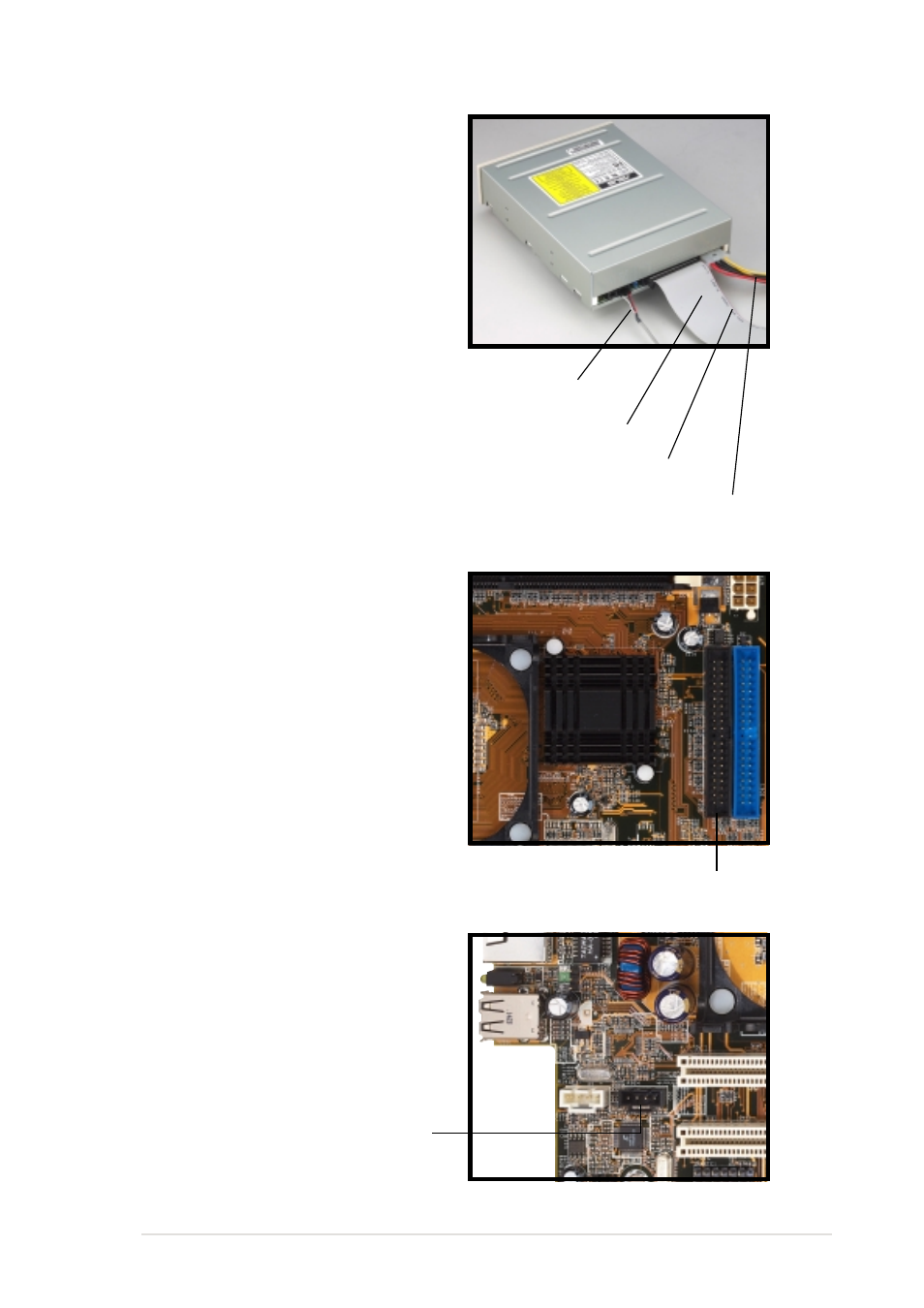
Connect a power cable from
the power supply to the power
connector at the back of the
CD-ROM. Use the cable with
the white connector labeled
P1.
6.
Connect one end of the IDE
ribbon cable to the IDE
interface at the back of the
CD-ROM, matching the red
stripe on the cable with Pin 1
on the IDE interface.
7.
Connect one end of the
CD-ROM audio cable to the
4-pin connector at the back of
the CD-ROM.
8.
Connect the other end of the
IDE ribbon cable to the
secondary IDE connector
(black connector labeled IDE2)
on the motherboard.
Red Stripe to Pin 1
IDE Ribbon Cable
Power Cable (P1)
CD-ROM Audio Cable
9.
Connect the other end of the
audio cable to the black 4-pin
connector labeled CD on the
motherboard.
CD-ROM Connector
(CD1)
Secondary IDE connector
(IDE2)
- CG8565 (410 pages)
- CG8565 (246 pages)
- CS5120 (1 page)
- CS5111 (26 pages)
- ET1611PUK (38 pages)
- S2-P8H61E (80 pages)
- P2-P5945GCX (90 pages)
- P2-PH1 (80 pages)
- P1-P5945G (80 pages)
- CG8270 (534 pages)
- CG8270 (362 pages)
- CG8270 (218 pages)
- CG8270 (536 pages)
- CG8270 (72 pages)
- CG8270 (76 pages)
- P3-P5G31 (100 pages)
- P3-PH4 (80 pages)
- P2-M2A690G (8 pages)
- P2-M2A690G (80 pages)
- P4-P5N9300 (82 pages)
- P4-P5N9300 (1 page)
- P2-P5945GC (92 pages)
- P1-P5945GC (92 pages)
- P3-P5G33 (98 pages)
- T3-P5945GC (80 pages)
- T3-P5945GCX (80 pages)
- P2-M2A690G (94 pages)
- T3-PH1 (82 pages)
- T3-PH1 (80 pages)
- T5-P5G41E (76 pages)
- T5-P5G41E (82 pages)
- S1-AT5NM10E (68 pages)
- P6-P7H55E (67 pages)
- ES5000 (174 pages)
- T4-P5G43 (104 pages)
- T-P5G31 (92 pages)
- BT6130 (60 pages)
- BT6130 (54 pages)
- BT6130 (2 pages)
- CG8265 (210 pages)
- CG8265 (350 pages)
- CM1740 (330 pages)
- CM1740 (70 pages)
- CM1740 (198 pages)
- P6-M4A3000E (59 pages)