Asus P5LD2 User Manual
Page 46
2 - 2 4
2 - 2 4
2 - 2 4
2 - 2 4
2 - 2 4
C h a p t e r 2 : H a r d w a r e i n f o r m a t i o n
C h a p t e r 2 : H a r d w a r e i n f o r m a t i o n
C h a p t e r 2 : H a r d w a r e i n f o r m a t i o n
C h a p t e r 2 : H a r d w a r e i n f o r m a t i o n
C h a p t e r 2 : H a r d w a r e i n f o r m a t i o n
4 .
4 .
4 .
4 .
4 .
S e r i a l A T A c o n n e c t o r s ( 7 - p i n S A T A 1 [ r e d ] , S A T A 2 [ r e d ] ,
S e r i a l A T A c o n n e c t o r s ( 7 - p i n S A T A 1 [ r e d ] , S A T A 2 [ r e d ] ,
S e r i a l A T A c o n n e c t o r s ( 7 - p i n S A T A 1 [ r e d ] , S A T A 2 [ r e d ] ,
S e r i a l A T A c o n n e c t o r s ( 7 - p i n S A T A 1 [ r e d ] , S A T A 2 [ r e d ] ,
S e r i a l A T A c o n n e c t o r s ( 7 - p i n S A T A 1 [ r e d ] , S A T A 2 [ r e d ] ,
S A T A 3 [ b l a c k ] , S A T A 4 [ b l a c k ] )
S A T A 3 [ b l a c k ] , S A T A 4 [ b l a c k ] )
S A T A 3 [ b l a c k ] , S A T A 4 [ b l a c k ] )
S A T A 3 [ b l a c k ] , S A T A 4 [ b l a c k ] )
S A T A 3 [ b l a c k ] , S A T A 4 [ b l a c k ] )
These connectors are for the Serial ATA signal cables for Serial ATA
hard disk drives.
If you installed Serial ATA hard disk drives, you can create a RAID 0,
RAID 1, RAID 5, or RAID 10 configuration with the Intel
®
Matrix
Storage Technology through the onboard Intel
®
ICH7R RAID controller.
Refer to Chapter 5 for details on how to set up Serial ATA RAID
configurations.
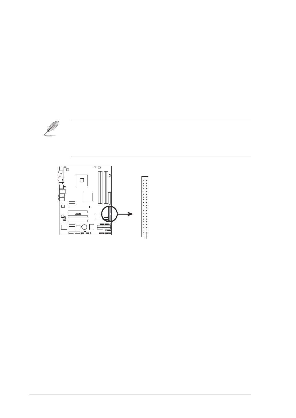
3 .
3 .
3 .
3 .
3 .
I C H 7 R P r i m a r y I D E c o n n e c t o r ( 4 0 - 1 p i n P R I _ I D E )
I C H 7 R P r i m a r y I D E c o n n e c t o r ( 4 0 - 1 p i n P R I _ I D E )
I C H 7 R P r i m a r y I D E c o n n e c t o r ( 4 0 - 1 p i n P R I _ I D E )
I C H 7 R P r i m a r y I D E c o n n e c t o r ( 4 0 - 1 p i n P R I _ I D E )
I C H 7 R P r i m a r y I D E c o n n e c t o r ( 4 0 - 1 p i n P R I _ I D E )
This connector is for an Ultra DMA 100/66 signal cable. The Ultra
DMA 100/66 signal cable has three connectors: a blue connector for
the primary IDE connector on the motherboard, a black connector for
an Ultra DMA 100/66 IDE slave device (optical drive/hard disk drive),
and a gray connector for an Ultra DMA 100/66 IDE master device (hard
disk drive). If you install two hard disk drives, you must configure the
second drive as a slave device by setting its jumper accordingly. Refer
to the hard disk documentation for the jumper settings.
•
Pin 20 on the IDE connector is removed to match the covered hole
on the Ultra DMA cable connector. This prevents incorrect insertion
when you connect the IDE cable.
•
Use the 80-conductor IDE cable for Ultra DMA 100/66 IDE devices.
P5LD2
®
P5LD2 IDE connector
NOTE: Orient the red markings
(usually zigzag) on the IDE
ribbon cable to PIN 1.
PRI_IDE
PIN 1