34 chapter 1: product introduction, P5vd2-vm se speaker out connector speaker, P5vd2-vm se analog front panel connector aafp – Asus P5VD2-VM SE User Manual
Page 46
1-34
Chapter 1: Product introduction
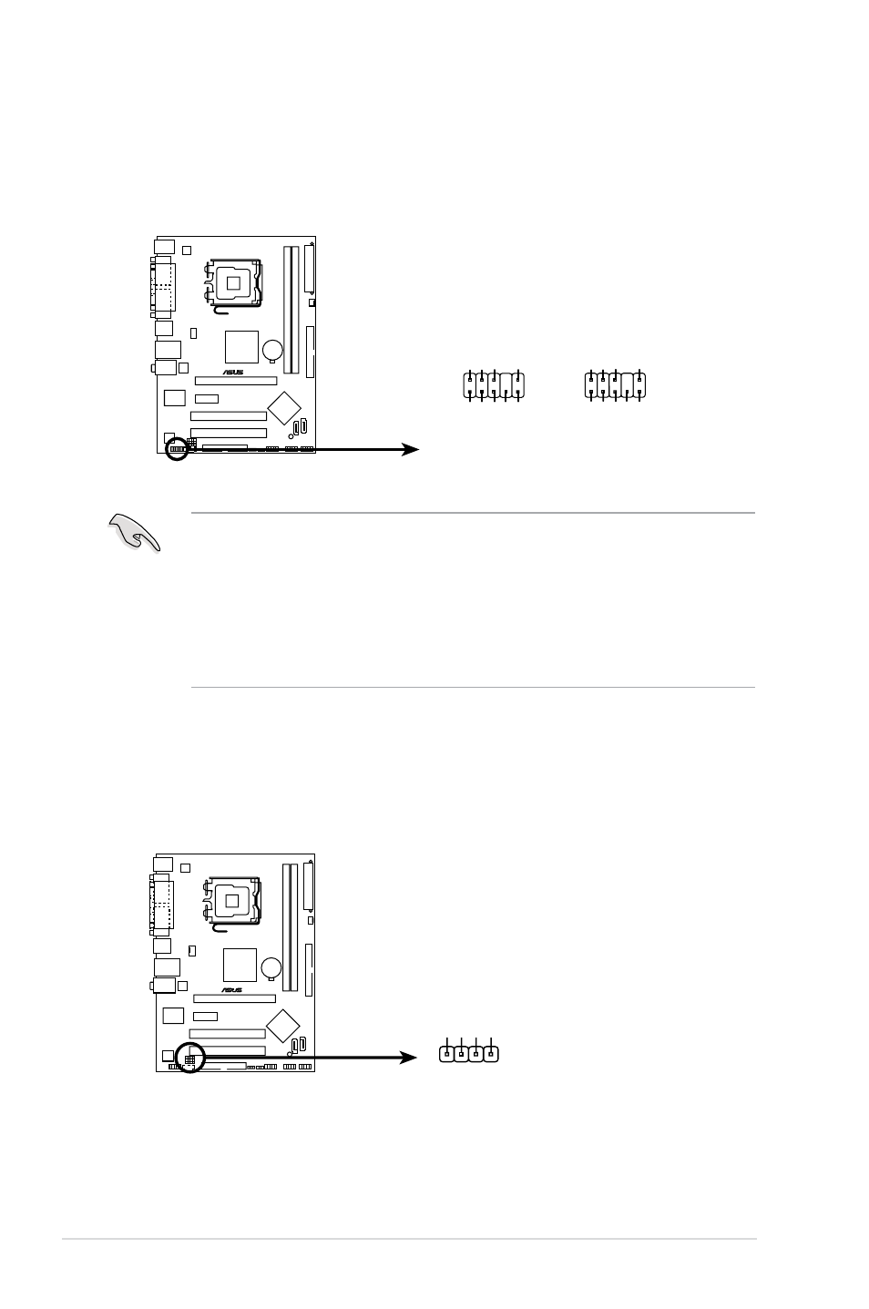
10. Front panel audio connector (10-1 pin AAFP)
This connector is for a chassis-mounted front panel audio I/O module that
supports either High Definition Audio or legacy AC ‘97 audio standard.
Connect one end of the front panel audio I/O module cable to this connector.
• Use a chassis that provides a high-definition audio front panel audio
I/O to use the high-definition audio features.
• If you want to connect a high-definition front panel audio module to this
connector, set the Front Panel Type item in the BIOS setup to [HD Audio];
if you want to connect an AC'97 front panel audio module to this connector,
set the item to [AC'97]. By default, this connector is set to [HD Audio]. See
section 2.4.4 Onboard Devices Configuration for details.
11. Speaker out connector (4-pin SPEAKER)
This 4-pin connector is for the chassis-mounted system warning speaker. The
speaker allows you to hear system beeps and warnings.
®
P5VD2-VM SE
P5VD2-VM SE Speaker out connector
SPEAKER
+5V
PIN1
GND Speak Ou
t
GND
®
P5VD2-VM SE
P5VD2-VM SE Analog front panel connector
AAFP
Legacy AC’97-compliant
pin definition
NC
MIC2
Line out_R
Line out_L
NC
NC
MICPWR
NC
AGND
POR
T1 R
SENSE2_RETUR
POR
T1 L
POR
T2 R
POR
T2 L
SENSE1_RETUR
SENSE_SEND
PRESENCE#
GND
Azalia-compliant
pin definition