Iii. installation, Map of the motherboard, 4asus p/i-p55sp4v user’s manual – Asus P/I-P55SP4V User Manual
Page 10: Map of board) iii. inst alla tion
4
ASUS P/I-P55SP4V User’s Manual
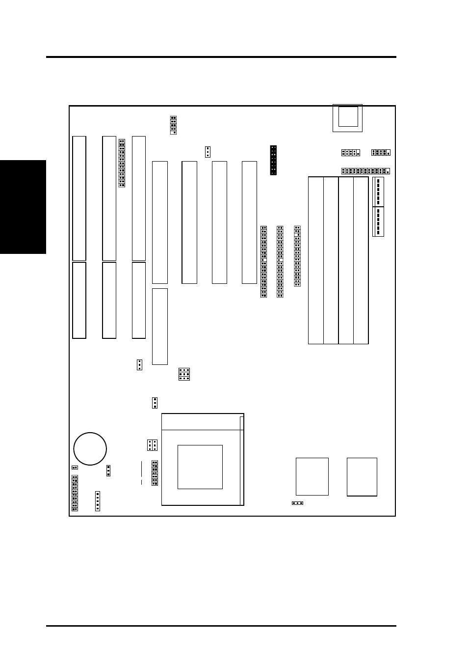
III. INSTALLATION
Map of the Motherboard
ISA
Slot 1
ISA
Slot 2
ISA
Slot 3
PCI Slot 4 / MediaBus 2.0
PCI Slot 3
PCI Slot 2
PCI Slot 1
Keyboard
Parallel Printer
SIMM Socket 4 (Bank 1)
SIMM Socket 3 (Bank 1)
SIMM Socket 2 (Bank 0)
SIMM Socket 1 (Bank 0)
512KB Onboard L2 Cache
Case Connections
Feature Connector
JP1
Multi-I/O
JP12
JP1
1
CPU to Bus Ratio
JP4
Linear/Burst Mode
COM 1
COM 2
Primary IDE
Secondary IDE
Floppy Drives
P54C CPU Volt
IDE_LED
#CR2032
3Volt Button
Cell Battery
VGA + PS/2
Card Connector
Universal Serial Bus
(Reserved for future use)
JP8
Boot Block Program
BUS Freq.
JP5
JP6
JP7
Infrared Conn
JP16
CMOS RAM
JP29
JP28
JP27
JP26
JP25
JP24
JP23
P55C CPU Volt
Board Power Input
P8
P9
12V CPU Fan Power
CPU ZIF Socket 7
(Map of Board)
III. INST
ALLA
TION
See also other documents in the category Asus Motherboard:
- P5B Premium Vista Edition (188 pages)
- P5B (140 pages)
- P5B (56 pages)
- P5KPL-VM/1394/SI (94 pages)
- M2N68-CM (28 pages)
- P5GD1-VM (92 pages)
- P5AD2-E Premium (2 pages)
- P5GD1-VM (88 pages)
- P5AD2 Premium (8 pages)
- DELUXE A7N8X-E (114 pages)
- P5KPL-AM SE (62 pages)
- P5KPL-AM SE (40 pages)
- P5KPL-AM SE (38 pages)
- P4S8X-X (64 pages)
- P5K-VM (98 pages)
- K8V-X SE (82 pages)
- M2N68-AM SE2 (40 pages)
- P4P800 SE (16 pages)
- P4P800 SE (125 pages)
- DELUXE SERIES M3A32-MVP (176 pages)
- P5AD2 Deluxe (148 pages)
- M4A79 Deluxe (122 pages)
- A7V266-E (108 pages)
- Application Manual (4 pages)
- Application Manual (8 pages)
- Application Manual (2 pages)
- Application Manual (6 pages)
- Application Manual (9 pages)
- Application Manual (3 pages)
- Application Manual (1 page)
- Application Manual (5 pages)
- Application Manual (11 pages)
- Application Manual (10 pages)
- M4A88T-I DELUXE (44 pages)
- M4A88T-I DELUXE (70 pages)
- P9X79 DELUXE (2 pages)
- RAMPAGE IV GENE (1 page)
- P9X79 (156 pages)
- P8H61-M PLUS V3 (64 pages)
- A85XM-A (78 pages)
- M4A78L-M LE (64 pages)
- M2N68-AM (96 pages)
- M2N68-AM (62 pages)
- M2N68-AM (38 pages)
- Blitz Formula (2 pages)