Asus P5KPL-C User Manual
Page 47
ASUS P5KPL-C
1-35
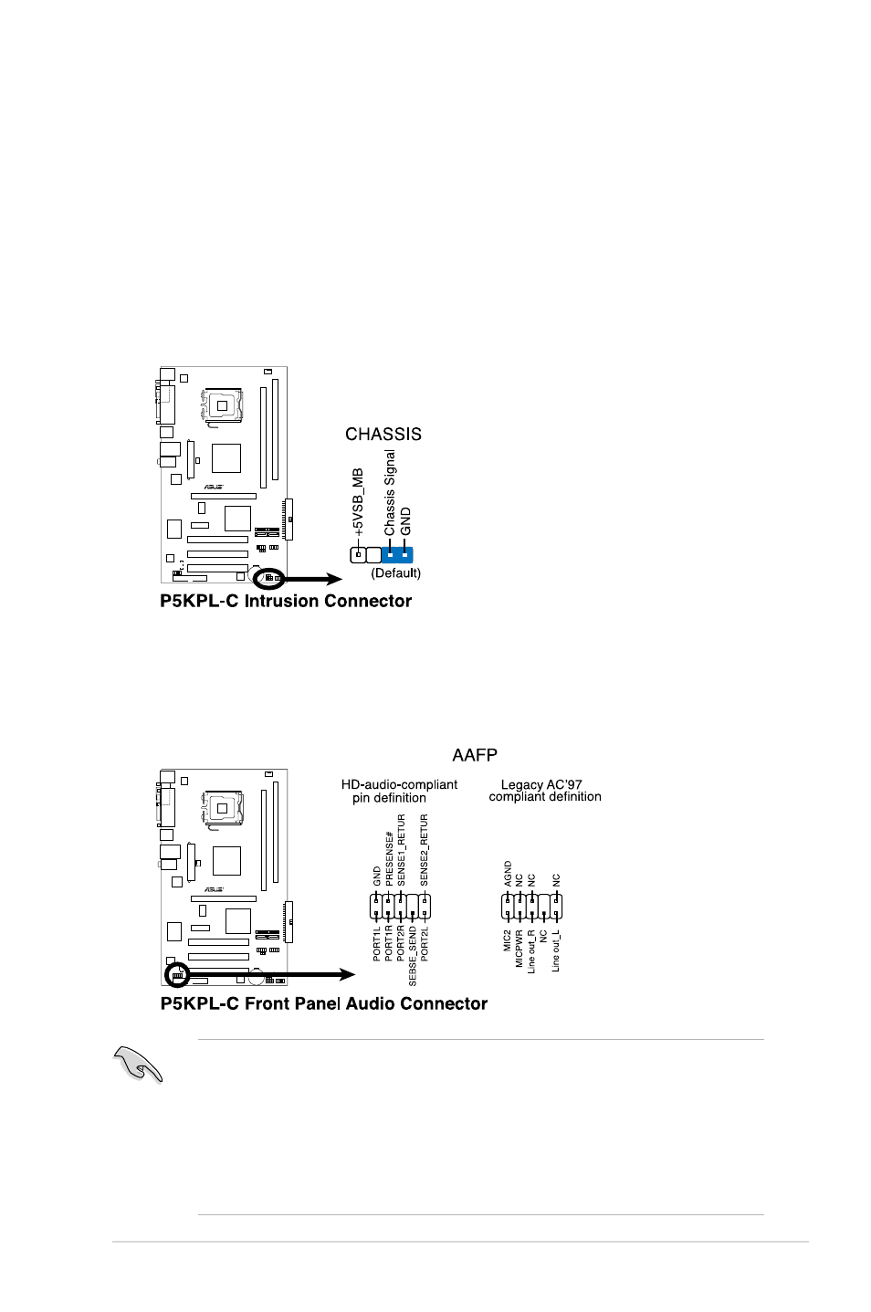
9. Front panel audio connector (10-1 pin AAFP)
This connector is for a chassis-mounted front panel audio I/O module that
supports either HD Audio or legacy AC’97 audio standard.
P5KPL-C
• We recommend that you connect a high-definition front panel audio
module to this connector to avail of the motherboard’s high-definition audio
capability.
• By default, this connector is set to HD Audio. If you want to connect an
AC97 front panel audio module to this connector, set the Front Panel
Support Type item in the BIOS to [AC97]. See section “2.4.4 Chipset” for
details.
8. Chassis intrusion connector (4-1 pin CHASSIS)
This connector is for a chassis-mounted intrusion detection sensor or switch.
Connect one end of the chassis intrusion sensor or switch cable to this
connector. The chassis intrusion sensor or switch sends a high-level signal to
this connector when a chassis component is removed or replaced. The signal
is then generated as a chassis intrusion event.
By default , the pin labeled “Chassis Signal” and “ Ground” are shorted with
a jumper cap. Remove the jumper caps only when you intend to use the
chassis intrusion detection feature.
P5KPL-C