Hardware setup, Asus p3c-d user’s manual 45 – Asus P3C-D User Manual
Page 45
ASUS P3C-D User’s Manual
45
3. HARDWARE SETUP
Connectors
3. H/W SETUP
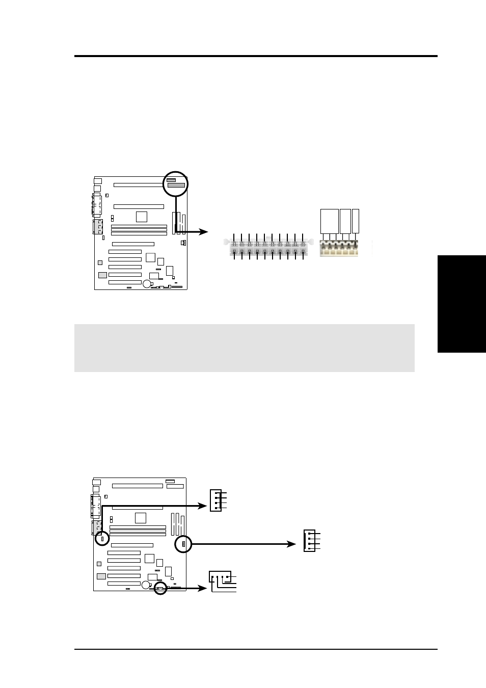
16) ATX & Auxiliary Power Supply Connectors (20-pin ATXPWR/6-pin AUXPWR)
The ATXPWR connector connects to an ATX power supply while the AUXPWR
connector connects to an auxiliary 3- or 5-volt power supply. The plug from
either power supply will only insert in one orientation because of the different
hole sizes, in the case of ATXPWR, or the distinct plastic guide pins on the lead,
in the case of AUXPWR. Find the proper orientation and push down firmly but
gently, making sure that the pins are aligned. Once aligned, press the lead onto
the connector until the lead locks into place.
P3C-D ATX & Auxiliary Power Connectors
AUXPWR
GND
+3V
+5V
ATXPWR
+3.3 V
olts
-12.0 V
olts
Ground
Power Supply On
Ground
Ground
Ground
-5.0 V
olts
+5.0 V
olts
+5.0 V
olts
Power Good
+12.0 V
olts
+3.3 V
olts
+3.3 V
olts
Ground
+5.0 V
olts
Ground
+5.0 V
olts
Ground
+5V Standby
P3C-D
IMPORTANT:
Make sure that your ATX power supply can supply at least 1A on
the 5-volt standby lead (5VSB). You may experience difficulty in powering on
your system if your power supply cannot provide enough current.
17) Internal Audio Connectors (4 pin MODEM, CD_IN, AUX))
These connectors allow you to receive stereo audio input from such sound sources
as a CD-ROM, TV tuner, or MPEG card. The MODEM connector allows the
onboard audio to interface with a voice modem card with a similar connector. It
also allows the sharing of mono_in (such as a phone) and mono_out (such as a
speaker) between the onboard audio and the voice modem card.
P3C-D
P3C-D Internal Audio Connectors
MODEM
AUX
Modem-In (to Modem)
Ground
Modem-Out (from Modem)
Ground
CD_IN
Right Audio Channel
Left Audio Channel
Ground
Ground
Left Audio Channel
Right Audio Channel
Ground
Ground