Hardware setup, 4 installing the processor – Asus P3C-D User Manual
Page 32
32
ASUS P3C-D User’s Manual
3. HARDWARE SETUP
CPU
3. H/W SETUP
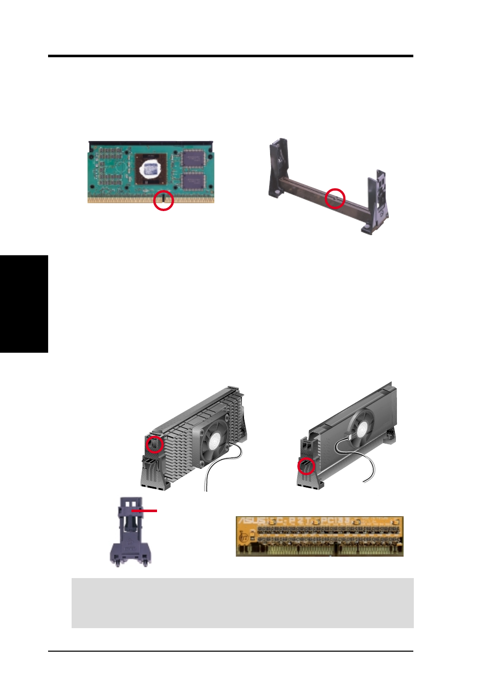
3.6.4 Installing the Processor
NOTE: The following steps assume that you have already attached the heatsink and
installed the URM into your motherboard.
1. Make sure that the processor substrate key is aligned with the Slot 1 connector key.
Substrate Key
Connector Key
2. Push down firmly but gently the SECC2/SECC/SEPP into the URM until it
snaps into place.
NOTE: The processor edge fingers must be kept parallel to the connector or else
misalignment will occur.
SECC for Pentium II only: Secure the SECC in place by pushing the two SECC
locks outward so that the locks show through the retention mechanism’s lock holes.
SECC2/SEPP: When engaged, the T-bars lock into the slots at the two ends of
the SECC2/SEPP heatsink.
SECC
SECC2/SEPP
CPU fan cable to
fan connector
CPU fan
cable to fan
connector
Lock hole
Lock hole
IMPORTANT:
If you are installing only one processor, install the processor in
CPU1 (Slot 1). You must terminate CPU2 (Slot 2) with the ASUS C-P2T PC133
CPU termination card to maintain signal strength.
ASUS C-P2T PC133 Termination Card
Locked Position
(push upward)