26 chapter 2: hardware information, Figure 2-35 chassis alarm lead – Asus P4B-FX User Manual
Page 46
2-26
Chapter 2: Hardware information
P4B-FX
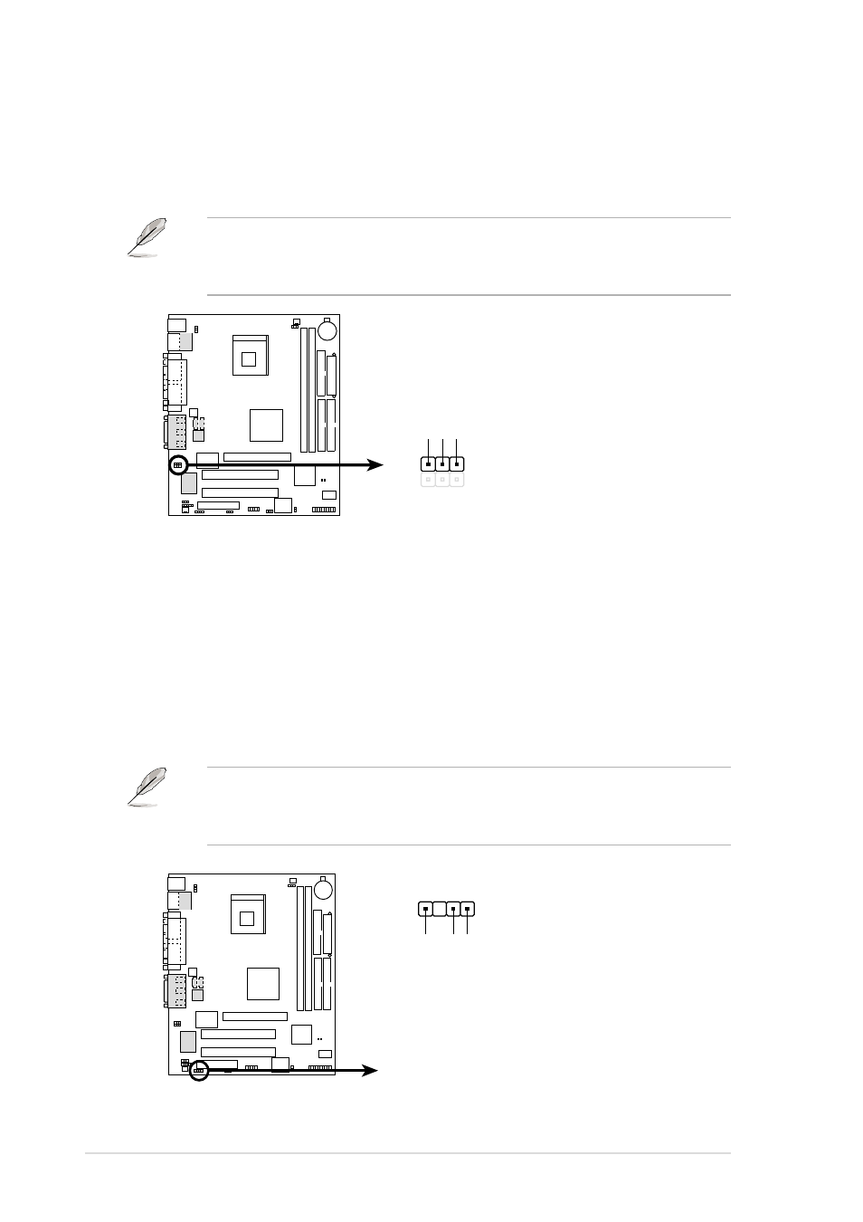
P4B-FX Internal Microphone Connector
MIC2
MIC Power
1
MIC Input
Ground
10. Internal microphone connector (3-pin MIC2)
(on audio models only)
This connector connects to an optional front panel audio module using
a 3-pin audio cable. If your chassis has this audio module, you can
connect a microphone to the front panel connector .
Figure 2-34
Internal Microphone Connector
The front panel microphone may not work properly when there is
another microphone connected to the Microphone (pink) jack on the
rear panel. You may only use one microphone at a time.
P4B-FX
P4B-FX Chassis Alarm Lead
CHASSIS
+5V
olt
(Power Supply Stand By)
Ground
Chassis Signal
1
11. Chassis alarm lead (4-1 pin CHASSIS)
This lead is for a chassis designed with intrusion detection feature.
This requires an external detection mechanism such as a chassis
intrusion sensor or microswitch. When you remove any chassis
component, the sensor triggers and sends a high-level signal to this
lead to record a chassis intrusion event.
If you do not wish to use the chassis intrusion lead, place a jumper cap
over the pins labeled “Chassis Signal” and “Ground” to close the
circuit.
Figure 2-35
Chassis Alarm Lead