2 motherboard layout, 2 chapter 2: hardware information, Figure 2-2 motherboard layout – Asus P4B-FX User Manual
Page 22: Pci1, Pci2, P 4 b - f x, Intel 845, Super i/o
2-2
Chapter 2: Hardware information
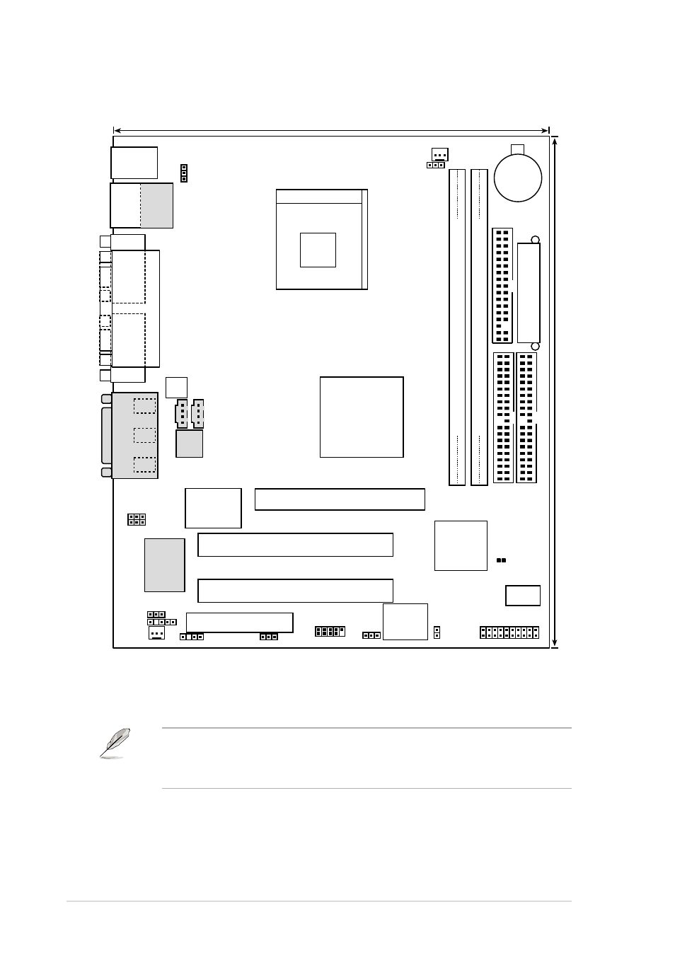
2.2
Motherboard layout
Figure 2-2
Motherboard Layout
The audio codec, external and internal audio connectors, and LAN
features are optional components. The components are grayed out in
the above motherboard layout.
19.2cm (7.56in)
22.9cm (9.01in)
FLOPPY
SECONDAR
Y
IDE
PRIMAR
Y
IDE
Intel I/O
Controller
Hub
(ICH2)
P 4 B - F X
Accelerated Graphics Port (AGP)
CR2032 3V
Lithium Cell
CMOS Power
A
TX Power Connector
2Mbit
Firmware
Hub
Super
I/O
Intel 845
Memory
Controller
Hub (MCH)
CPU_FAN
SYSTEM
1
1
1
DIMM Socket 1 (64/72-bit, 168-pin module)
0 1
DIMM Socket 2 (64/72-bit, 168-pin module)
2 3
ATX12V
AUX
CD1
Socket 478
PCI1
PS/2KBMS
T: Mouse
B: Keyboard
Audio
Codec
Realtek
R
TL8100B
RJ-45
Top:
USB1
USB2
Bottom:
COM1
P
ARALLEL
PORT
COM2
GAME_AUDIO
Mic
In
Line
Out
Line
In
PCI2
CNR_SLOT
PANEL
USB2
KBPWR
USBPWR01
IDELED
USBPWR23
AUD_EN1
CHASIS
LAN_EN
IR_CN
MIC2
HPHONE
ASUS
ASIC
CLRTC
- P5B (140 pages)
- P5B (56 pages)
- P5B Premium Vista Edition (188 pages)
- P5KPL-VM/1394/SI (94 pages)
- M2N68-CM (28 pages)
- P5AD2 Premium (8 pages)
- P5GD1-VM (92 pages)
- P5AD2-E Premium (2 pages)
- P5GD1-VM (88 pages)
- DELUXE A7N8X-E (114 pages)
- P5KPL-AM SE (40 pages)
- P5KPL-AM SE (38 pages)
- P5KPL-AM SE (62 pages)
- P4S8X-X (64 pages)
- P5K-VM (98 pages)
- K8V-X SE (82 pages)
- M2N68-AM SE2 (40 pages)
- P4P800 SE (125 pages)
- P4P800 SE (16 pages)
- DELUXE SERIES M3A32-MVP (176 pages)
- P5AD2 Deluxe (148 pages)
- M4A79 Deluxe (122 pages)
- A7V266-E (108 pages)
- Application Manual (6 pages)
- Application Manual (9 pages)
- Application Manual (3 pages)
- Application Manual (1 page)
- Application Manual (5 pages)
- Application Manual (11 pages)
- Application Manual (10 pages)
- Application Manual (4 pages)
- Application Manual (8 pages)
- Application Manual (2 pages)
- M4A88T-I DELUXE (70 pages)
- M4A88T-I DELUXE (44 pages)
- P9X79 (156 pages)
- P9X79 DELUXE (2 pages)
- RAMPAGE IV GENE (1 page)
- P8H61-M PLUS V3 (64 pages)
- A85XM-A (78 pages)
- M4A78L-M LE (64 pages)
- M2N68-AM (38 pages)
- M2N68-AM (96 pages)
- M2N68-AM (62 pages)
- Blitz Extreme (188 pages)