Asus A7S266-VM/U2 User Manual
Page 27
ASUS A7S266-VM Motherboard
1-17
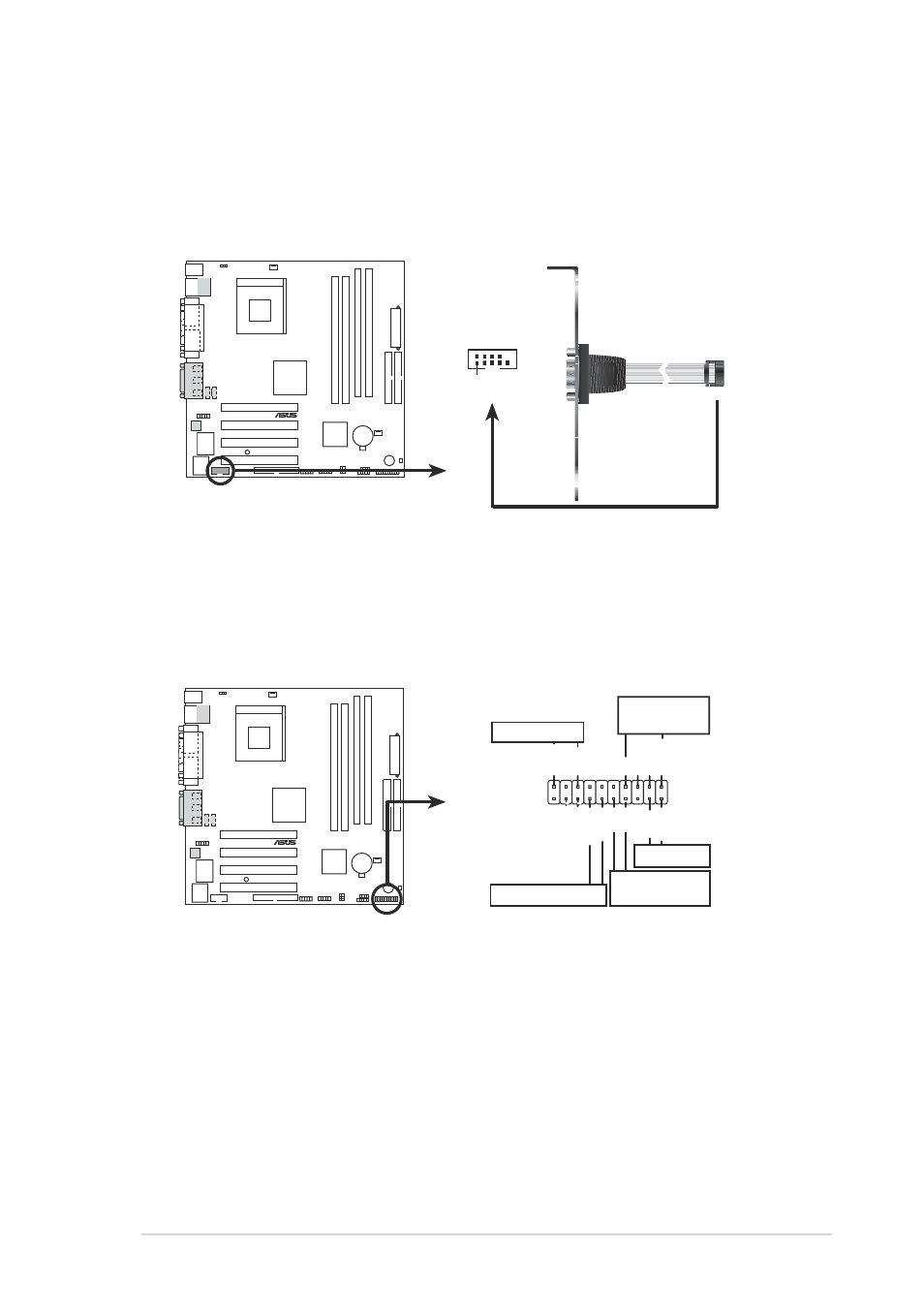
12. Serial connector (9-pin COM2 )
This 9-pin connector connects to the Serial COM2 bracket. Connect
the COM2 cable to this connector and install the bracket on an
available slot in the rear panel of the chassis.
A7S266-VM
®
A7S266-VM Serial COM2 Bracket
PIN 1
COM2
13. System panel connector (20-pin PANEL1)
This connector accommodates several system front panel functions.
•
System Power LED Lead (2-pin PLED)
This 2-pin connector connects to the system power LED. The LED
lights up when you turn on the system power.
•
System Warning Speaker Lead (4-pin SPEAKER)
This 4-pin connector connects to the case-mounted speaker and
allows you to hear system beeps and warnings.
A7S266-VM
®
A7S266-VM System Panel Connectors
*
Requires an ATX power supply.
PLED-
Ground
MLED-
PWR
PLED+
+5V
Speaker
Speaker
Connector
Power LED
Ground
MLED+
Reset SW
SMI Lead
Message LED
ExtSMI#
GND
Reset
Ground
Ground
ATX Power
Switch*