Asus P5GD1-VM User Manual
Page 35
A S U S P 5 G D 1 - V M
A S U S P 5 G D 1 - V M
A S U S P 5 G D 1 - V M
A S U S P 5 G D 1 - V M
A S U S P 5 G D 1 - V M
1 - 2 5
1 - 2 5
1 - 2 5
1 - 2 5
1 - 2 5
•
The system automatically assigns the boot sequence of ATAPI
devices connected to the PCI IDE connector.
•
The ITE
®
8211F controller supports a maximum of two Ultra ATA
devices.
•
If you attach any IDE or ATAPI device to the PRI_PCIIDE1 connector,
prepare a driver disk with the ITE
®
8211F controller before installing
the operating system.
•
We recommend that you connect the hard disk to the PRI_PCIIDE1
connector (black) and connect an optical drive to the PRI_IDE (blue)
connector for better performance and convenience.
3 .
3 .
3 .
3 .
3 .
P C I I D E c o n n e c t o r ( 4 0 - 1 p i n P R I _ P C I I D E 1 )
P C I I D E c o n n e c t o r ( 4 0 - 1 p i n P R I _ P C I I D E 1 )
P C I I D E c o n n e c t o r ( 4 0 - 1 p i n P R I _ P C I I D E 1 )
P C I I D E c o n n e c t o r ( 4 0 - 1 p i n P R I _ P C I I D E 1 )
P C I I D E c o n n e c t o r ( 4 0 - 1 p i n P R I _ P C I I D E 1 )
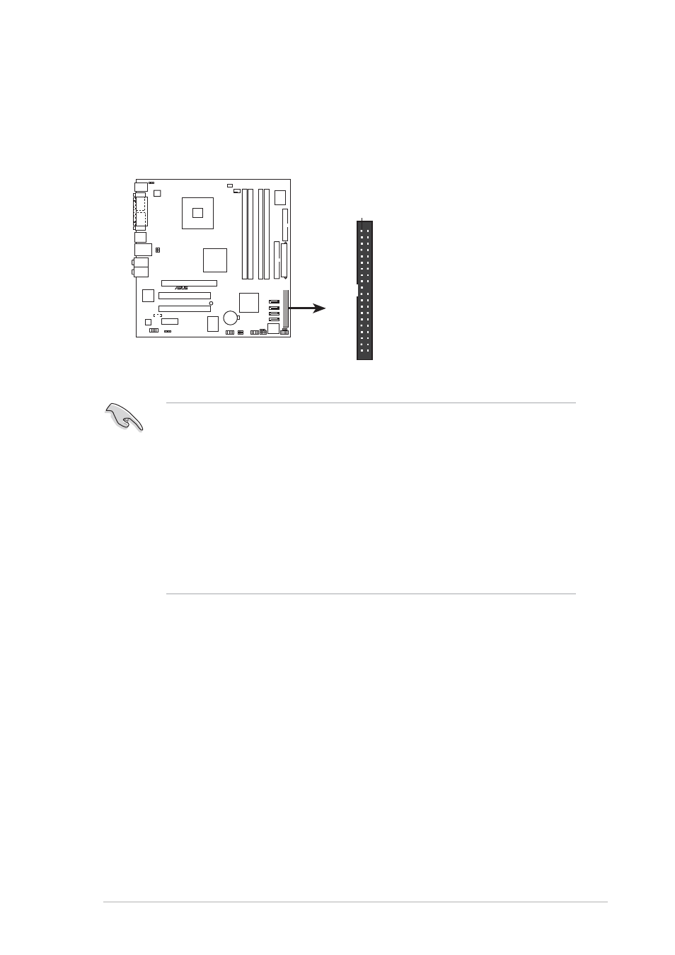
This connector is for an Ultra DMA 133/100/66 signal cables. The IDE
connector supports up to two IDE devices (optical drive and hard disk
drive).
P5GD1-VM
®
P5GD1-VM PCI IDE connector
NOTE: Orient the red markings
(usually zigzag) on the IDE
cable to PIN 1.
PIN 1
PRI_PCIIDE1