Asus P5GD1-VM User Manual
Page 23
A S U S P 5 G D 1 - V M
A S U S P 5 G D 1 - V M
A S U S P 5 G D 1 - V M
A S U S P 5 G D 1 - V M
A S U S P 5 G D 1 - V M
1 - 1 3
1 - 1 3
1 - 1 3
1 - 1 3
1 - 1 3
1.7
System memory
1.7.1
1.7.1
1.7.1
1.7.1
1.7.1
DIMM sockets location
DIMM sockets location
DIMM sockets location
DIMM sockets location
DIMM sockets location
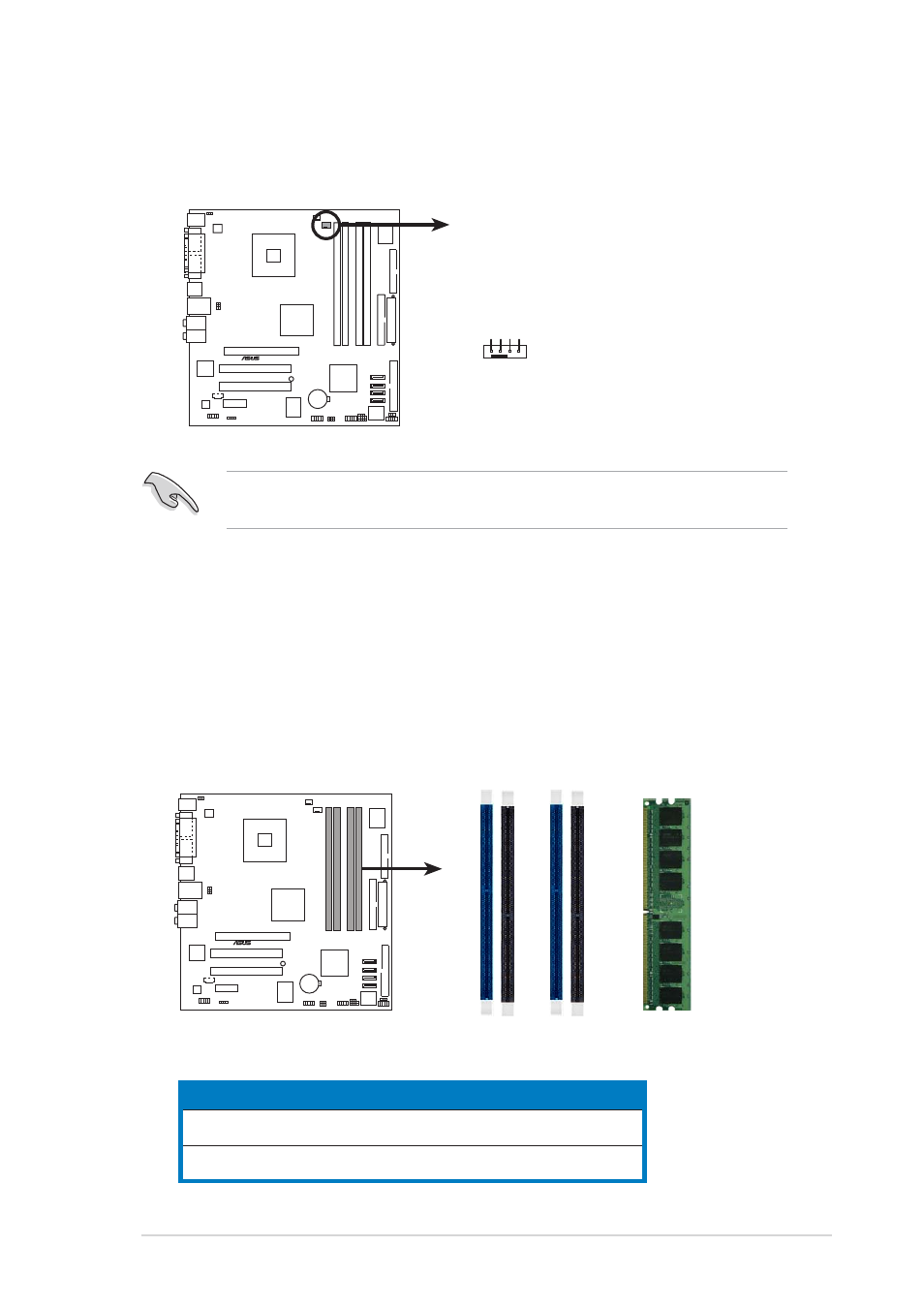
The motherboard comes with four 184-pin Double Data Rate (DDR) Dual
Inline Memory Modules (DIMM) sockets.
The following figure illustrates the location of the sockets:
P5GD1-VM
®
P5GD1-VM 184-Pin DDR DIMM Sockets
DIMM_A1
DIMM_A2
DIMM_B1
DIMM_B2
4.
When the fan and heatsink assembly is in place, connect the CPU fan
cable to the connector on the motherboard labeled CPU_FAN.
Do not forget to connect the CPU fan connector! Hardware monitoring
errors can occur if you fail to plug this connector.
P5GD1-VM
®
CPU_FAN1
GND CPU F
AN PWR
CPU F
AN IN
CPU F
AN PWM
C h a n n e l
C h a n n e l
C h a n n e l
C h a n n e l
C h a n n e l
S o c k e t s
S o c k e t s
S o c k e t s
S o c k e t s
S o c k e t s
C o l o r
C o l o r
C o l o r
C o l o r
C o l o r
C h a n n e l A
C h a n n e l A
C h a n n e l A
C h a n n e l A
C h a n n e l A
D I M M _ A 1 a n d D I M M _ B 1
D I M M _ A 1 a n d D I M M _ B 1
D I M M _ A 1 a n d D I M M _ B 1
D I M M _ A 1 a n d D I M M _ B 1
D I M M _ A 1 a n d D I M M _ B 1
B l u e
B l u e
B l u e
B l u e
B l u e
C h a n n e l B
C h a n n e l B
C h a n n e l B
C h a n n e l B
C h a n n e l B
D I M M _ A 2 a n d D I M M _ B 2
D I M M _ A 2 a n d D I M M _ B 2
D I M M _ A 2 a n d D I M M _ B 2
D I M M _ A 2 a n d D I M M _ B 2
D I M M _ A 2 a n d D I M M _ B 2
B l a c k
B l a c k
B l a c k
B l a c k
B l a c k