2 internal connectors, Internal connectors -11, C60m1-i atx power connectors – Asus C60M1-I User Manual
Page 21
1-11
Chapter 1: Product introduction
6.
USB 2.0 ports 1 and 2. These two 4-pin Universal Serial Bus (USB) ports are for USB
2.0/1.1 devices.
7.
USB 2.0 ports 3 and 4. These two 4-pin Universal Serial Bus (USB) ports are for USB
2.0/1.1 devices.
8.
DVI-D port. This port is for any DVI-D compatible device. DVI-D can’t be converted to
output RGB Signal to CRT and isn’t compatible with DVI-I.
9.
Video Graphics Adapter (VGA) port. This 15-pin port is for a VGA monitor or other
VGA-compatible devices.
10. USB 2.0 ports 5 and 6. These two 4-pin Universal Serial Bus (USB) ports are for USB
2.0/1.1 devices.
1.7.2
Internal connectors
• For a fully configured system, we recommend that you use a power supply unit (PSU)
that complies with ATX 12 V Specification 2.0 (or later version) and provides a minimum
power of 350 W.
• DO NOT forget to connect the 4-pin ATX +12V power plug. Otherwise, the system will
not boot up.
• We recommend that you use a PSU with higher power output when configuring a
system with more power-consuming devices. The system may become unstable or may
not boot up if the power is inadequate.
• If you are uncertain about the minimum power supply requirement for your system,
refer to the Recommended Power Supply Wattage Calculator at http://support.asus.
com/PowerSupplyCalculator/PSCalculator.aspx?SLanguage=en-us for details.
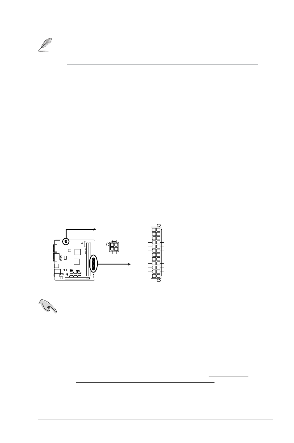
1.
ATX power connectors (24-pin EATXPWR, 4-pin ATX12V)
These connectors are for ATX power supply plugs. The power supply plugs are
designed to fit these connectors in only one orientation. Find the proper orientation and
push down firmly until the connectors completely fit.
C60M1-I
C60M1-I ATX power connectors
EATXPWR
ATX12V
PIN 1
GND
+5 Volts
+5 Volts
+5 Volts
-5 Volts
GND
GND
GND
PSON#
GND
-12 Volts
+3 Volts
+3 Volts
+12 Volts
+12 Volts
+5V Standby
Power OK
GND
+5 Volts
GND
+5 Volts
GND
+3 Volts
+3 Volts
PIN 1
+12V DC
+12V DC
GND
GND
To configure an 8-channel audio output:
Use a chassis with HD audio module in the front panel to support an 8-channel audio
output.