28 chapter 2: hardware information, P5k/epu usb 2.0 connectors, Usb1112 – Asus P5K/EPU User Manual
Page 52: Usb910
2-28
Chapter 2: Hardware information
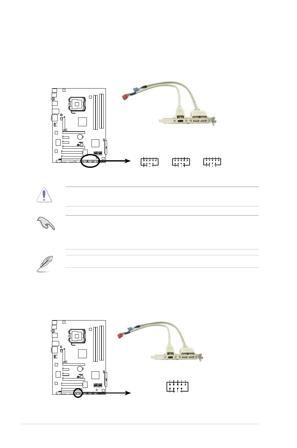
4. USB connectors (10-1 pin USB 78, USB 9 10, USB 11 12)
These connectors are for USB 2.0 ports. Connect the USB module cable
to any of these connectors, then install the module to a slot opening at the
back of the system chassis. These USB connectors comply with USB 2.0
specification that supports up to 480 Mbps connection speed.
P5K/EP
U
®
P5K/EPU USB 2.0 connectors
USB+5V USB_P12- USB_P12+ GN
D
NC
USB+5V
USB_P1
1-
USB_P1
1+
GN
D
PIN1
USB1112
USB+5V USB_P10- USB_P10+ GN
D
NC
USB+5
V
USB_P9- USB_P9+
GN
D
PIN1
USB910
USB+5V USB_P8
-
USB_P8
+
GN
D
NC
USB+5
V
USB_P7- USB_P7+
GN
D
PIN1
USB78
Never connect a 1394 cable to the USB connectors. Doing so will damage the
motherboard!
5. IEEE 1394a port connector (10-1 pin IE1394_2)
This connector is for a IEEE 1394a port. Connect the IEEE 1394a module
cable to this connector, then install the module to a slot opening at the back
of the system chassis.
P5K/EP
U
®
P5K/EPU IEEE 1394a connector
IE1394_2
PIN 1
TP
A1
-
GND TPB1
-
+12V GND
TP
A1
+
GND
TPB1
+
+12V
If your chassis suppots front panel USB ports, you can attach a front panel
USB cable to these connectors. Connect the USB cable to ASUS Q-Connector
(USB, blue) first, and then install the Q-Connector (USB) to the USB connector
onboard.
The USB module cable is purchased separately.