Bypass modes, Optical bypass switch with heartbeat, Figure 4: bypass enabled – Net Optics Optical Bypass Switch w_Heartbeat User Manual
Page 8: Figure 5: bypass disabled
4
Optical Bypass Switch with Heartbeat
Bypass Modes
The Optical Bypass Switch with Heartbeat bypasses attached in-line device
when one of three events occurs:
• Power loss to the switch
• Link failure
• Application failure
Two LEDs on the front of the Optical Bypass Switch indicate whether the
switch is bypassing the connected appliance or not . When the Bypass ON
indicator is illuminated, the bypass switch has not received the heartbeat
packet as expected and is in Bypass Enabled mode . When the Bypass OFF
indicator is illuminated, the bypass switch is in Bypass Disabled mode and is
sending traffic through the attached in-line device.
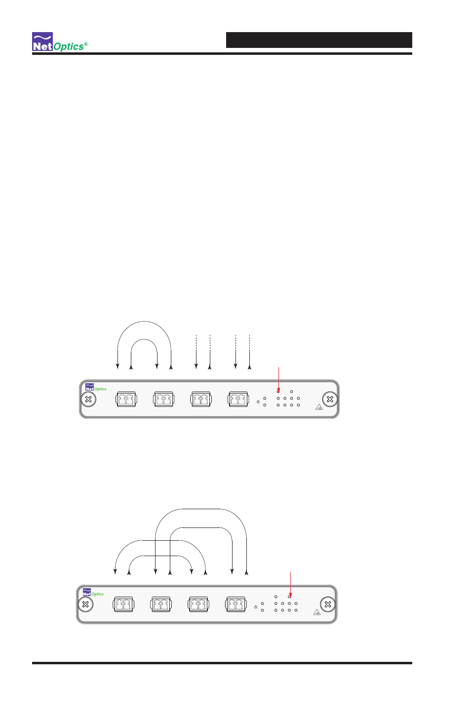
When the switch is in Bypass Enabled (ON) mode, the switch circuitry
re-directs network traffic around the in-line appliance. In Bypass Enabled
mode Network Ports A and B are connected (see Figure 4).
Figure 4: Bypass Enabled
When the switch is in Bypass Disabled (OFF) mode, the switch circuitry
sends network traffic through the in-line appliance. In Bypass Disabled mode,
Network Port A is connected to Monitor Port C and Network Port B is con-
nected to Monitor Port D (see Figure 5).
Figure 5: Bypass Disabled
www.netoptics.com
®
Optical Bypass Switch
LASER
CAUTION!
2
1
BYPASS
ON
OFF
ACT
LINK
B
1
2
A
OUT
IN
OUT
IN
OUT
IN
OUT
IN
Network
Monitor
A
B
1
2
Tx Rx
Tx Rx
Tx Rx
Tx Rx
Bypass Mode Enabled (ON)
www.netoptics.com
®
Optical Bypass Switch
LASER
CAUTION!
2
1
BYPASS
ON
OFF
ACT
LINK
B
1
2
A
OUT
IN
OUT
IN
OUT
IN
OUT
IN
Network
Monitor
A
B
1
2
Tx Rx
Tx Rx
Tx Rx
Tx Rx