Connecting to the in-line device, Optical bypass switch with heartbeat, Figure 7: connecting to the in-line device – Net Optics Optical Bypass Switch w_Heartbeat User Manual
Page 17
13
Optical Bypass Switch with Heartbeat
Connecting to the In-line Device
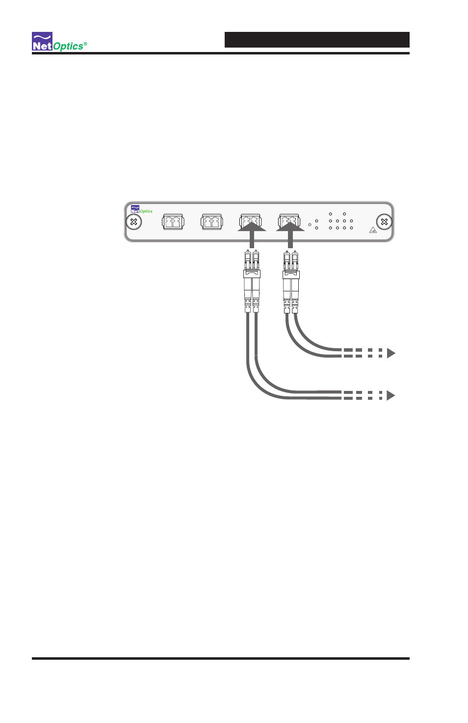
To connect the bypass switch to the in-line device:
1. Connect Monitoring Port C to the in-line appliance using a duplex LC fiber
cable. This acts as your DCE interface.
2. Connect Monitoring Port D to the in-line appliance using a duplex LC fiber
cable. This acts as your DTE interface.
Figure 7: Connecting to the In-Line Device
3. Verify that the bypass switch Monitoring Ports are cabled in-line to the
attached device .
4. Connect power to the switch. If you are implementing power fault failover,
make sure you connect the switches' power supplies to the same power
sources that the IPS is using.
www.netoptics.com
®
Optical Bypass Switch
LASER
CAUTION!
2
1
BYPASS
ON
OFF
ACT
LINK
B
1
2
A
OUT
IN
OUT
IN
OUT
IN
OUT
IN
Network
Monitor
A
B
1
2
Rx
B
To monitoring device
To monitoring device
Tx
A