Dayton Audio BR-1 6-1 User Manual
Page 11
Page 11
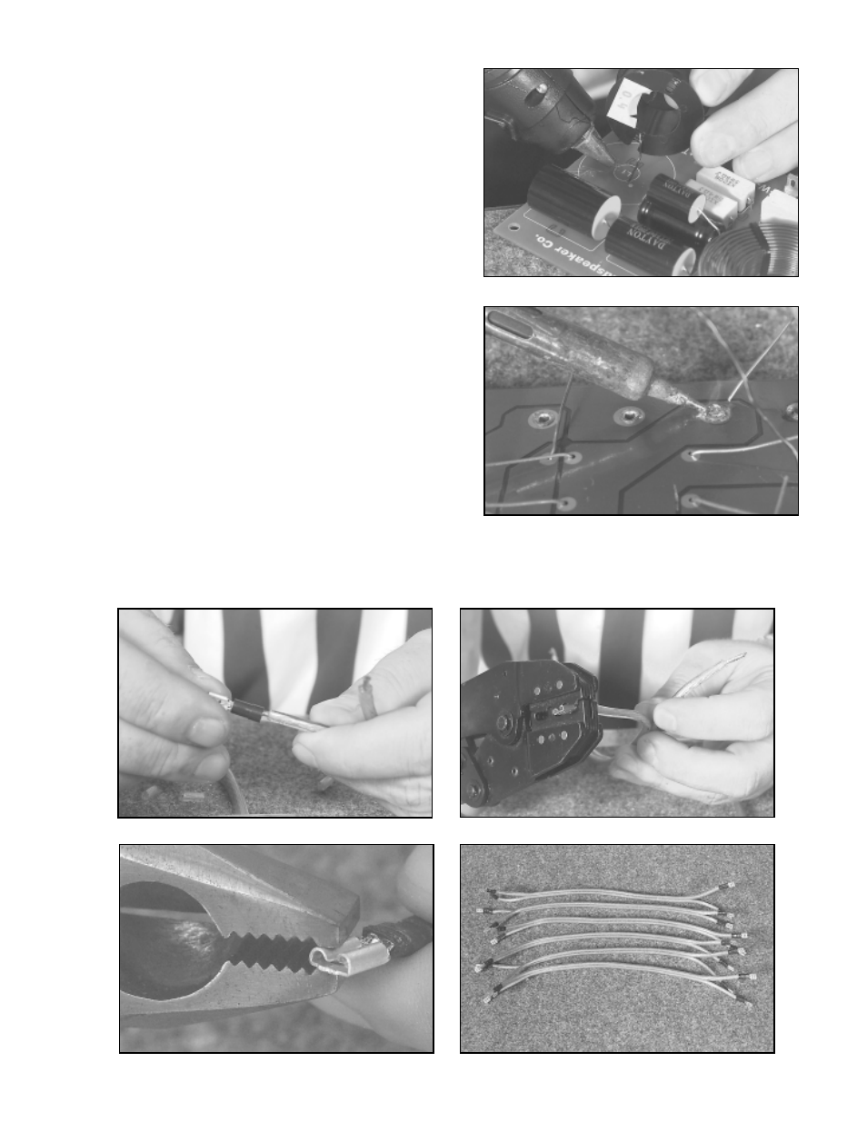
4.
Solder all component connections on the p.c. board
using silver or electronics grade (60/40) solder. At
this time, you should also solder the riveted .205
terminal connections. A properly soldered connection
appears shiny and smooth. We recommend using a
soldering iron with a wattage rating between 20-
30watts. Using wire cutters, trim off all excess
component leads.
5.
Cut the supplied wire into 6 pieces approximately 12"
long. Strip the insulation on all wires back
about 3/8"-1/2".
6.
Using a crimp tool, crimp the .205 terminals on the wire leads. To ensure a tight connection, gently squeeze
the push on terminals with a small pair of pliers. Note: If you prefer, you can solder the wires directly to the
p.c. board and drivers instead of using the connectors.
3.
To help reduce the risk of components rattling on the
p.c. board, (especially the inductors) use RTV
sealant or hot glue to mount the components to the
p.c. board. We recommend using hot glue due to its
faster setup time. If you use RTV sealant, you may
need to let it setup over night, before proceeding
with the assembly.