Dayton Audio BR-1 6-1 User Manual
Page 10
2.
When positioning components try to keep lead lengths to a minimum. Note: The (L1).40mH inductor should
be mounted on its side to minimize the interaction between the two coils on the board. You can trim the
length of the leads on the (L1) inductor without effecting its’ value. Using a utility knife, scrape off the enamel
coating on the trimmed lead ends so it will accept solder.
BR-1 Assembly Instructions
1) Installation Tools Needed
•
Phillips Screwdriver
•
Wire Cutter / Stripper
•
Hot glue/gun or RTV Sealant
•
Small pliers
•
Soldering iron
•
Crimp tool
•
Silver or Electronic grade solder
•
Utility knife
Crossover Assembly Note
Warning!! The correct assembly and wiring of the crossovers is critical to the proper operation of this speaker
system. In a worst case situation, an improperly wired network can damage your receiver or amplifier! Please
double and triple check all values and wiring.
Assembling the Crossovers
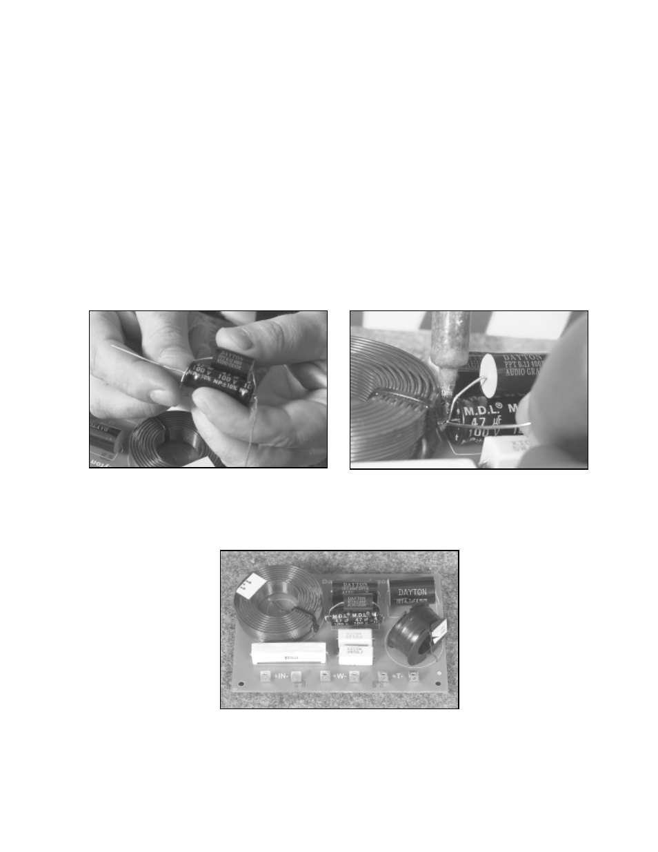
1.
Install all components on the boards in their proper location. When installing R1, position it so that air can
circulate around its body. Before mounting (C3) to the p.c. board, it needs to be “bypassed”. C3 is actually
two capacitors, one 47mfd. electrolytic bypassed with a .10mfd Dayton poly film/foil. This was done to
improve the acoustics of the electrolytic capacitor. To bypass the capacitor, simply parallel the two capacitors
together and wrap the smaller “poly” cap leads around the larger electrolytic cap leads and solder. Trim
excess “poly” cap leads and use the electrolytic leads to mount the “bypassed cap” to the p.c. board.
Page 10