Led indicators, Serial ports, Data bit – SENA Parani-SD1100 User Manual
Page 13: Reset to factory defaults
13
3.2. LED Indicators
Serial-Tx and Serial-Rx LED will flash accordingly when data is transmitted. For small data
transmissions, it may be hard to recognize the quick flashing action of the LED.
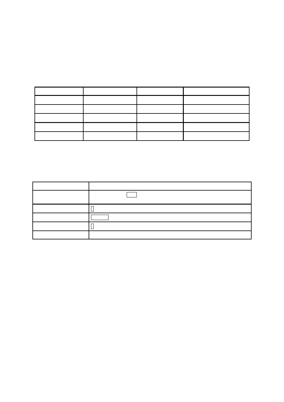
Table 3-2 The Parani-SD1100 LED Indicators
Indicator
Power LED
Standby LED
Connect LED
Mode0
Green┏━━━━━
Red┏━━━━━
Mode1
Green┏━━━━━
Green (every 1 sec) ┏┓
Mode2
Green┏━━━━━
Green (every 3 sec) ┏┰┓
Mode3
Green┏━━━━━
Green (every 3 sec) ┏┰┰┓
Connected
Green┏━━━━━
Green┏━━━━━
3.3. Serial Ports
The applicable settings for serial ports are as follows.
Table 3-3 The Parani-SD1100 Serial Port Settings
Serial Port Settings
Values
Baudrate
1200, 2400, 4800, 9600, 14400, 19200, 38400, 57600, 115200, 230400, 460800,
921600
Data bite
8
Parity
No parity, Even parity, Odd parity
Stop bit
1, 2
Hardware Flow Control
No Use
The values in box are the factory defaults. The flow control setting is configurable only through dip
switch.
3.4. Data Bit
Parani-SD1100 supports only 8 data bit. In the case of 7 data bit and even/odd parity, use SD 8 data
bit and none parity. At this time, master and slave are Parani-SD, Parani-ESD or Parani-MSP series.
But 7 data bit and none parity is not support.
3.5. Reset to Factory Defaults
To set all the configuration settings to its factory default parameters, press the reset button, depicted in
Fig. 3-1. Press and hold (for at least 1 sec) the reset button with a narrow pointed tool like paper clip.
Reset works only when power is on.