Getting started, 1 panel layout – SENA Rhio232 User Manual
Page 9
9
2. Getting Started
This chapter describes how to set up and configure the Rhio232 in the first place.
- 2.1 Panel Layout explains the panel layout and LED indicators.
- 2.2 Connecting the Hardware describes how to set up DIN rail mount kit and how to connect
the power and the serial device to the Rhio232.
Following items are required to get started.
- DIN rail mount kit (included in the package).
- CAT5 cable for configuration or connecting device server (included in the package).
- RJ45 to DB9 Female connector for configuration or connecting device server (included in the
package).
2.1 Panel Layout
The Rhio232 has LED indicator lamps for status display. The lamps in the left hand side
indicate the system power-on status, Serial Rx and Serial Tx for RS232 communication status.
There are 10 lamps for displaying digital output status, 12 lamps for digital input status, and
lamps for 4 analog port status. Table 2-1 shows the description of the indicator lamps of the
Rhio232.
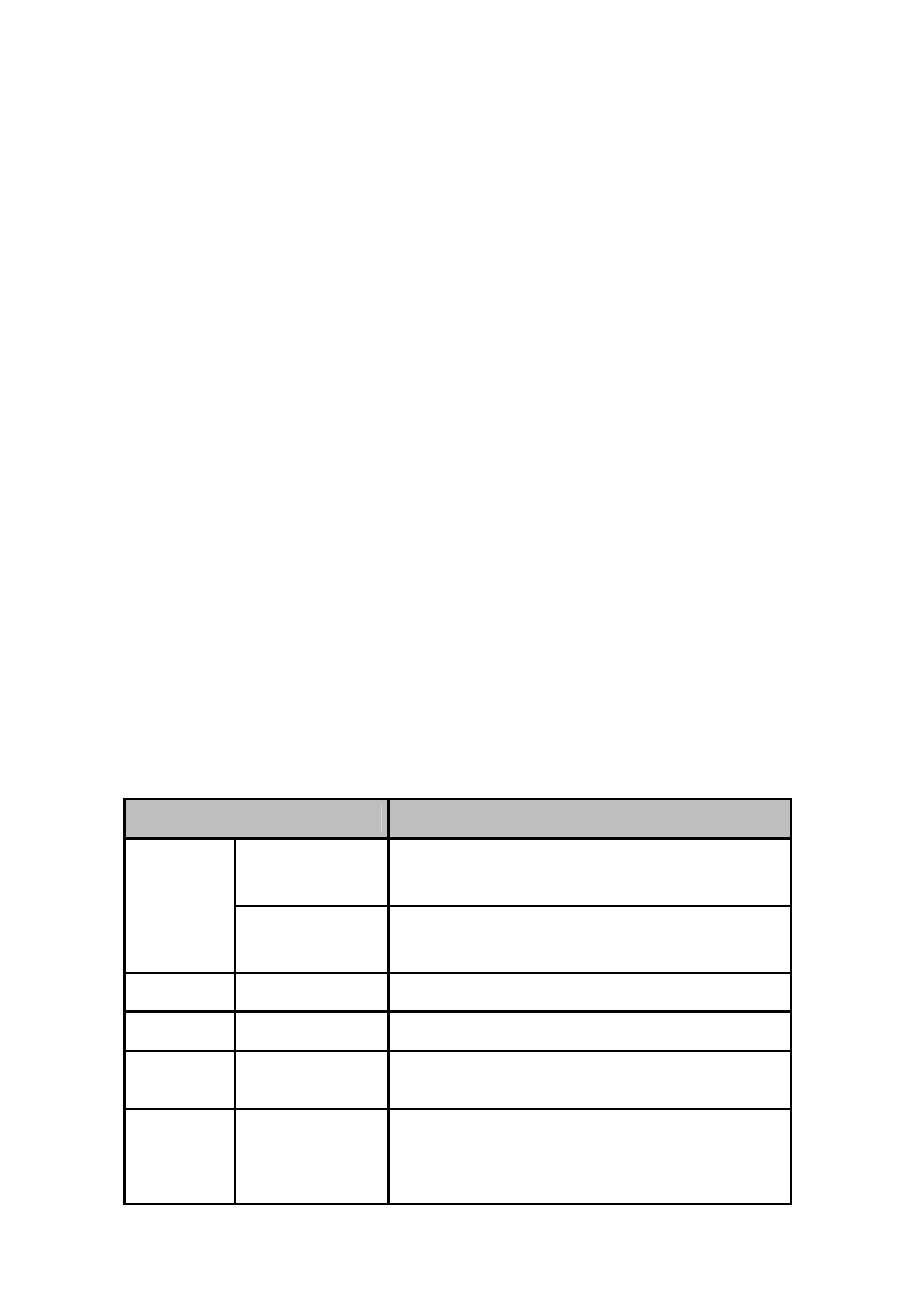
Table 2-1. LED indicator lamps
Lamps
Function
Link
Turned on to Green if connected to 10 Base-T Ethernet
network.
10Base-T
Act
Blink whenever there is any activities such as incoming
or outgoing packets through the Rhio10 Ethernet port
Staus
Power
Turned on to RED if power is supplied
Digital Input
DI 1 ~ DI 12
Turned on to GREEN if input status
Digital Output
DO 1 ~ DO 10
Turned on to GREEN if output status
Analog Input
AI 1 ~ AI 4
In Level Input mode, it is turned on to GREEN if the
value is larger than 512. In Switch Input mode, it is
turned on to GREEN if it is larger than threshold value.