Set-up – Ocean Optics Multimode Spectrum User Manual
Page 12
2: Set-up and Operation
Set-up
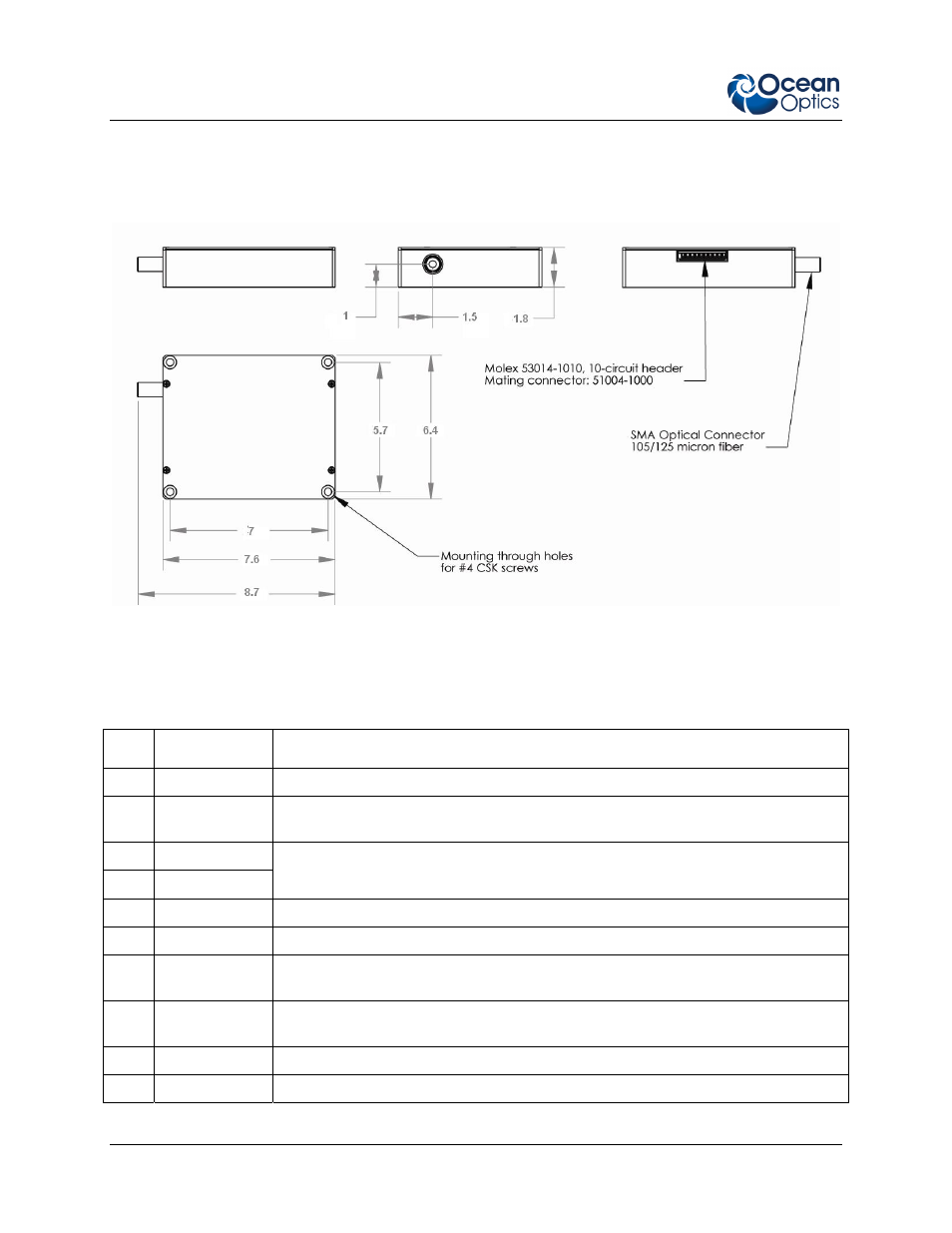
Refer to the following figure and table of pinouts while setting up your laser.
Laser Mechanical Drawing
Module Pinouts
Pin # Symbol
Description
1 NC
Not
connected
2
V set ENABLE Enables “LD SET” on Pin 8 when connected to Ground. If left open or set to 3 –
5 Volt, output power defaults to internally preset value.
3 T
SENS
4 T
SENS
1000 Ohm RTD sensor (with reference to Ground) to monitor module case.
5 GND
Ground
6
+ 5V
4.9 to 5.1 Volt; 1 Ampere
7
ENABLE
Tie to GND to disable laser output. Keep unconnected or apply 3 – 5 Volt to
enable laser output.
8
LD SET
Apply 0 to 1 Volt to control optical output power. Pin 2 must be grounded to
enable this option.
9 PD+
Photodiode
anode
10 PD-
Photodiode
cathode
4
LASER-785-IP -01-1208
- Apex 785 Raman (1 page)
- STS-UV (2 pages)
- TR2 Engineering Note (4 pages)
- SAD500 Communications and Control (19 pages)
- Red Tide USB650 Install (26 pages)
- Fiber Optic Termination Kit (6 pages)
- Transmissive pH Probe (10 pages)
- Remora (42 pages)
- PlasCalc (59 pages)
- Correcting Device Driver Issues (8 pages)
- ecoVis Krypton Light Source (16 pages)
- LPC-500CM (28 pages)
- HPX-2000 (24 pages)
- ADC1000-USB (27 pages)
- Torus Operating Instructions (30 pages)
- ADC2000-PCI (13 pages)
- Sensors for Real-Time Analysis (2 pages)
- IDRaman reader (2 pages)
- DH-2000-CAL (30 pages)
- QE65 Pro (32 pages)
- Collimating Lenses (2 pages)
- D1000 (2 pages)
- IDRaman mini (2 pages)
- HR2000CG-UV-NIR (42 pages)
- Cool Red (1 page)
- HL-2000 (20 pages)
- XE-1 Xenon (6 pages)
- USB-ADP Serial Adapters (3 pages)
- CHEM2000 (36 pages)
- Deuterium-Halogen Calibration Light Source (19 pages)
- NeoFox Engineering Note (30 pages)
- QE Pro (2 pages)
- OOIBase32 (140 pages)
- AR-1 Argon (6 pages)
- pH Sensor Patches, Probes and Cuvettes (36 pages)
- SpecLine Offline Spectroscopy (60 pages)
- HL-2000-HP-232 (26 pages)
- External Triggering Options Instructions for Spectrometers with Firmware Version 3.0 and Above (16 pages)
- Breakout Box (10 pages)
- USB-ISS-UV_VIS (4 pages)
- ISS-UV_VIS (6 pages)
- OOIColor (14 pages)
- LS-1 Series (12 pages)
- Apex Install (24 pages)
- DH-2000 (34 pages)