Light source connection and operation, Db15 connector – Ocean Optics LLS Series LED User Manual
Page 4
LLS Series Installation and Operation Instructions
4
300-00000-011-01-201301
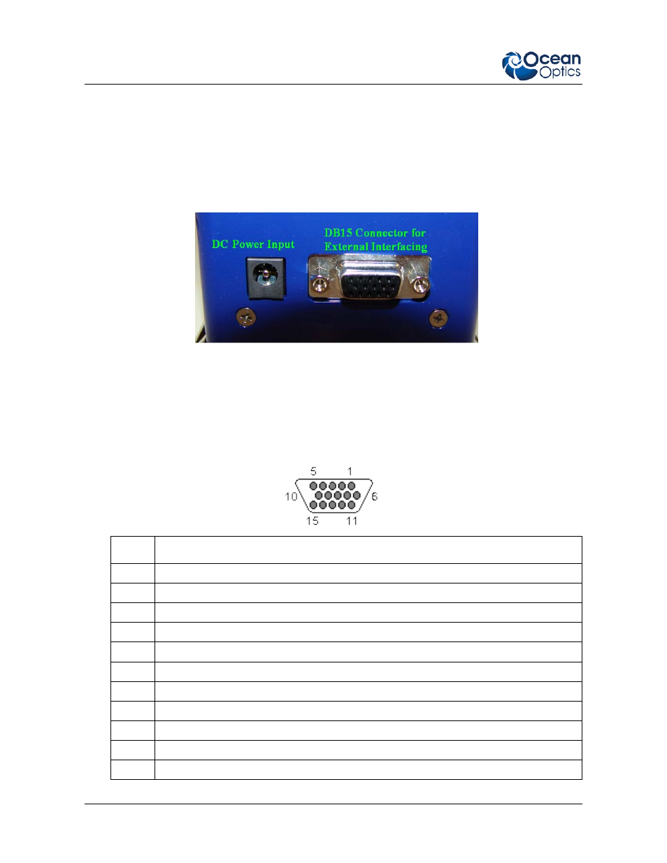
Light Source Connection and Operation
External interface is accomplished through a female high density DB15 connector. All external signals
are TTL compatible and will work with 3.3V or 5V logic. Please see
for a complete
list of pins.
The lamp can be externally turned off when in continuous mode by controlling pin 3. The signal is
internally pulled high and will return to ON when no low level signal is present.
Rear View of Cool Red Light Source
Pin 1 is the external trigger for pulse mode. See
External Triggering and Control
information. Never modulate this pin with a greater duty cycle and current than recommended by
the LED manufacturer as damage to the LED can result.
DB15 Connector
Pin #
Description
1
Pulsed input (rising edge). Use for pulsed mode
2
Pulse end output. This pin goes high at the end of the internal fixed length pulse.
3
Lamp enable (used in CW only)
4
5 volt output. Can be used to power external controller.
5
Address line A1 (for onboard EEPROM) 24LC64
6
Address line A2 (for onboard EEPROM) 24LC64
7
SCL for I2C EEPROM
8
SDA for I2C EEPROM
9
Ground
10
Ground
11
3.3V input for I2C EEPROM (required for accessing memory)