Ocean Optics ADC1000 ISA-bus User Manual
Page 6
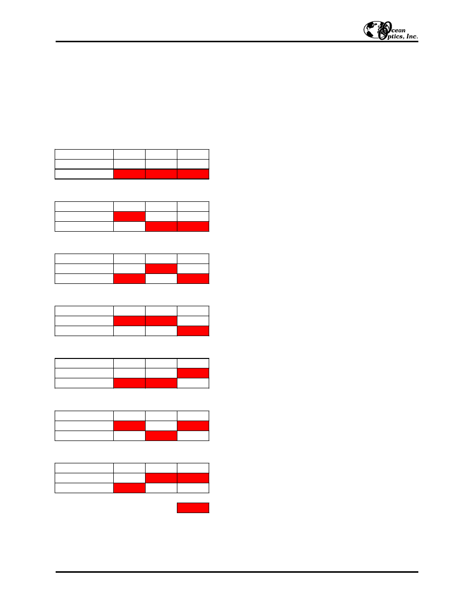
Changing the Interrupt Request Settings for the ADC1000 and PC2000
To change the IRQ settings on the ADC1000 and PC2000, see the bank of switches on the A/D board: The IRQ
may be changed via the last 3 switches. The following matrix defines the different IRQ settings by switch positions
7, 8, and 9. In the default setting, the IRQ is set to 7. Other combinations for IRQ settings are below. After you
have changed the switches, reinstall the card and change the software settings to match the hardware settings. (See
pages 1-4 for instructions.) The gray block indicates the position of the switch.
Installation Instructions: ADC1000 & PC2000 (for Windows 95/98 Users)
- 6 -
Switch #
7
8
9
ON
OFF
Switch #
7
8
9
ON
OFF
Switch #
7
8
9
ON
OFF
Switch #
7
8
9
ON
OFF
Switch #
7
8
9
ON
OFF
Switch #
7
8
9
ON
OFF
Switch #
7
8
9
ON
OFF
Interrupt Request 7 (Default Setting)
Interrupt Request 5
Interrupt Request 3
sw itch is in the on, upw ard position =
Interrupt Request 9
Interrupt Request 10
Interrupt Request 11
Interrupt Request 4
- Apex 785 Raman (1 page)
- STS-UV (2 pages)
- TR2 Engineering Note (4 pages)
- SAD500 Communications and Control (19 pages)
- Red Tide USB650 Install (26 pages)
- Fiber Optic Termination Kit (6 pages)
- Transmissive pH Probe (10 pages)
- Remora (42 pages)
- PlasCalc (59 pages)
- Correcting Device Driver Issues (8 pages)
- ecoVis Krypton Light Source (16 pages)
- LPC-500CM (28 pages)
- HPX-2000 (24 pages)
- ADC1000-USB (27 pages)
- Torus Operating Instructions (30 pages)
- ADC2000-PCI (13 pages)
- Sensors for Real-Time Analysis (2 pages)
- IDRaman reader (2 pages)
- DH-2000-CAL (30 pages)
- QE65 Pro (32 pages)
- Collimating Lenses (2 pages)
- D1000 (2 pages)
- IDRaman mini (2 pages)
- HR2000CG-UV-NIR (42 pages)
- Cool Red (1 page)
- HL-2000 (20 pages)
- XE-1 Xenon (6 pages)
- USB-ADP Serial Adapters (3 pages)
- CHEM2000 (36 pages)
- Deuterium-Halogen Calibration Light Source (19 pages)
- NeoFox Engineering Note (30 pages)
- QE Pro (2 pages)
- OOIBase32 (140 pages)
- AR-1 Argon (6 pages)
- pH Sensor Patches, Probes and Cuvettes (36 pages)
- SpecLine Offline Spectroscopy (60 pages)
- HL-2000-HP-232 (26 pages)
- External Triggering Options Instructions for Spectrometers with Firmware Version 3.0 and Above (16 pages)
- Breakout Box (10 pages)
- USB-ISS-UV_VIS (4 pages)
- ISS-UV_VIS (6 pages)
- OOIColor (14 pages)
- LS-1 Series (12 pages)
- Apex Install (24 pages)
- DH-2000 (34 pages)