Pin accessory connector pinout diagram – Ocean Optics QE65 Pro User Manual
Page 28
B: Specifications
22
220-12200-000-02-201303
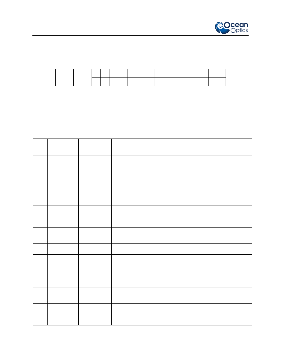
30-Pin Accessory Connector Pinout Diagram
When facing the 30-pin Accessory Connector on the front of the vertical wall of the QE65 Pro, pin
numbering is as follows:
USB
Port
2
4
6
8
10
12
14
16
18
20
22
24
26
28
30
1
3
5
7
9
11
13
15
17
19
21
23
25
27
29
30-Pin Accessory Connector Pinout Diagram
30-Pin Accessory Connector – Pin Definitions and
Descriptions
The following table contains information regarding the function of each pin in the QE65 Pro’s 30-Pin
Accessory Connector:
Pin
#
Function
Input/Output
Description
1
RS232 Rx
Input
RS232 receive signal – Communicates with a PC over DB9 Pin 3
2
RS232 Tx
Output
RS232 transmit signal – Communicates with a PC over DB9 Pin 2
3
GPIO (2)
Input/Output
General purpose software-programmable, digital input/output
(channel number)
4
N/A
N/A
Reserved
5
Ground
Input/Output
Ground
6
I
2
C SCL
Input/Output
I
2
C clock signal for communication to other I
2
C peripherals
7
GPIO (0)
Input/Output
General purpose software-programmable, digital input/output
(channel number)
8
I
2
C SDA
Input/Output
I
2
C data signal for communication to other I
2
C peripherals
9
GPIO (1)
Input/Output
General purpose software-programmable, digital input/output
(channel number)
10
Ext. Trigger
In
Input
TTL input trigger signal -- See External Triggering Options
document for info
11
GPIO (3)
Input/Output
General purpose software-programmable, digital input/output
(channel number)
12
V
CC
or 5V
IN
Input or
Output
Input power pin for QE65 Pro – When operating via USB, this pin
can power other peripherals – Ensure that peripherals comply with
USB specifications (no TEC power)