5 advanced features and options, Attenuation in db – Crown Audio CTs Series (2 Channel) User Manual
Page 9
Operation Manual
CTs Power Amplifiers
page 16
page 17
CTs Power Amplifiers
Operation Manual
5 Advanced Features
and Options
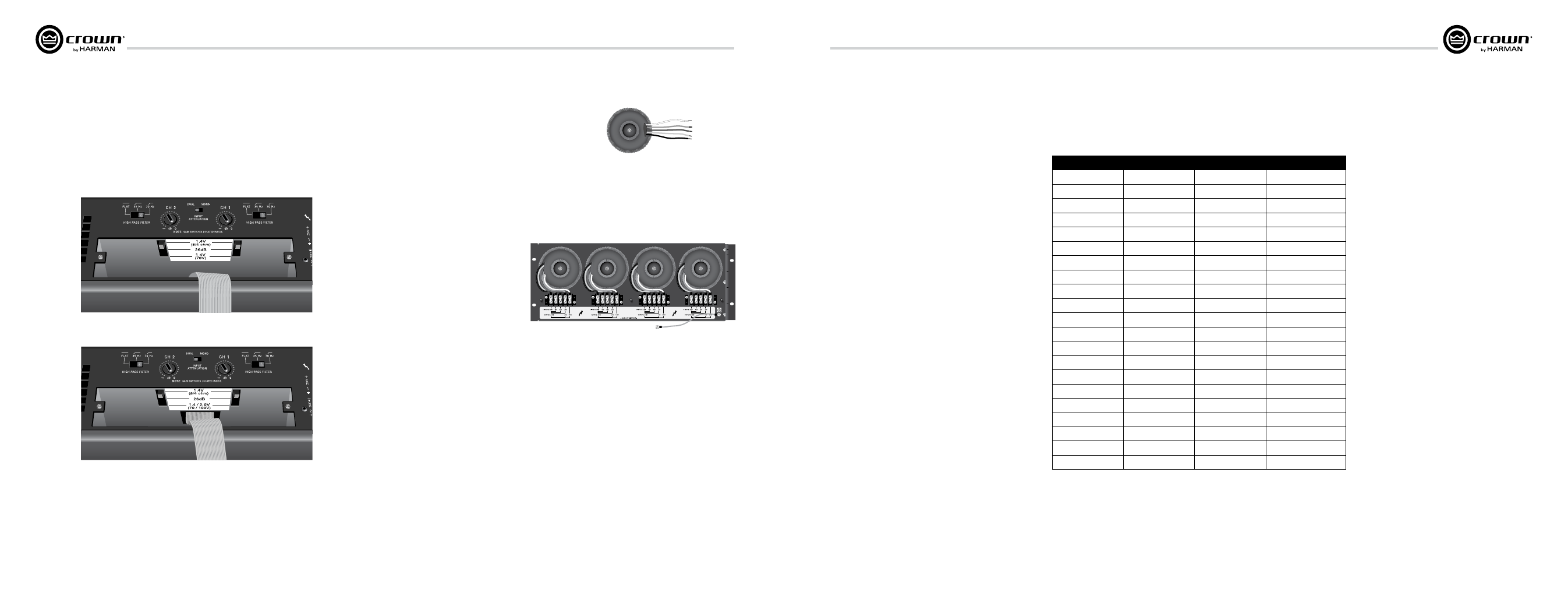
5.2.4 Input Sensitivity Switches
See Figures 5.1 and 5.2. To access the Input Sensitivity Switches, turn off the
amplifier and remove the PIP2-BBY Input Panel. The switches are in the top surface
of the cavity behind the Input Panel. One 3-position switch per channel selects
among these settings: CTs 600/1200: 1.4V (8/4 ohms), 26 dB gain, and 1.4V (70V
operation). CTs 2000/3000: 1.4V (8/4 ohms), 26 dB gain, and 1.4V (70V) / 2V
(100V). The Specifications chapter lists the input sensitivity for the 26 dB gain
set ting.
5.3 Options
T-170V: See Figure 5.3. This is an autoformer that
allows 100V output from the CTs 600/1200, and allows
other amplifiers without direct constant voltage output
to be easily integrated into distributed systems.
TP-170V: See Figure 5.4. This is a rack-mountable
panel with four autoformers as described above.
PiP Modules
Versatile PIP (Programmable Input Processor)
mod ules provide flexible expansion features that can
be added to customize the amplifier. PIP modules plug
into the connector inside the back panel of the
ampli fier. PIP modules are available with features
ranging from error-driven compressor/limiters to
crossovers to remote control and monitoring via
IQwic™ or System Architect software. Your amplifier is
a PIP2 amplifier, which means it can take advantage of
the many advanced features found in PIP2 modules.
The CTs Series 2-channel models do not accept earlier
PIP
modules.
Visit the Crown website at www.crownaudio.com, or
contact Crown Customer Service, for descriptions of
available PIP and PIP2 modules.
Figure 5.2 Input Sensitivity Switches for CTs 2000/3000
Figure 5.1 Input Sensitivity Switches for CTs 600/1200
Figure 5.3 T-170V
Figure 5.4 TP-170V (back view)
5 Advanced Features
and Options
5.3.1 Nominal Attenuation Settings
The signal level for each input can be attenuated repeatably by
adjusting the 21-step Level Control (see Section 4.3). Figure 5.5
shows the attenuation in dB for each detent. The setting of the
input-sensitivity switch varies the actual attenation as shown.
detent
26 dB
Tolerance (dB)
4/8 ohm or 70/100V
0 (full CCW)
OFF
—
OFF
1
48.0
±6
54.0
2
36.0
±6
42.0
3
24.0
±3
30.0
4
21.0
±3
26.0
5
18.0
±3
24.0
6
15.0
±3
22.0
7
13.5
±3
20.0
8
12.0
±1.5
18.0
9
10.5
±1.5
16.0
10
9.0
±1.5
14.5
11
8.0
±1.5
13.0
12
7.0
±1.5
11.0
13
6.0
±1
9.5
14
5.0
±1
8.0
15
4.0
±1
6.5
16
3.0
±1
5.0
17
2.0
±1
3.5
18
1.0
±1
1.5
19
0.5
+1 –5
0.5
20 (full CW)
0.0
—
0.0
Figure 5.1 Level-control Attenuation per Detent for CTs 2-Channel Amplifiers
attenuation in dB