4 operation, 5 advanced features and options – Crown Audio CTs Series (2 Channel) User Manual
Page 8
Operation Manual
CTs Power Amplifiers
page 14
page 15
CTs Power Amplifiers
Operation Manual
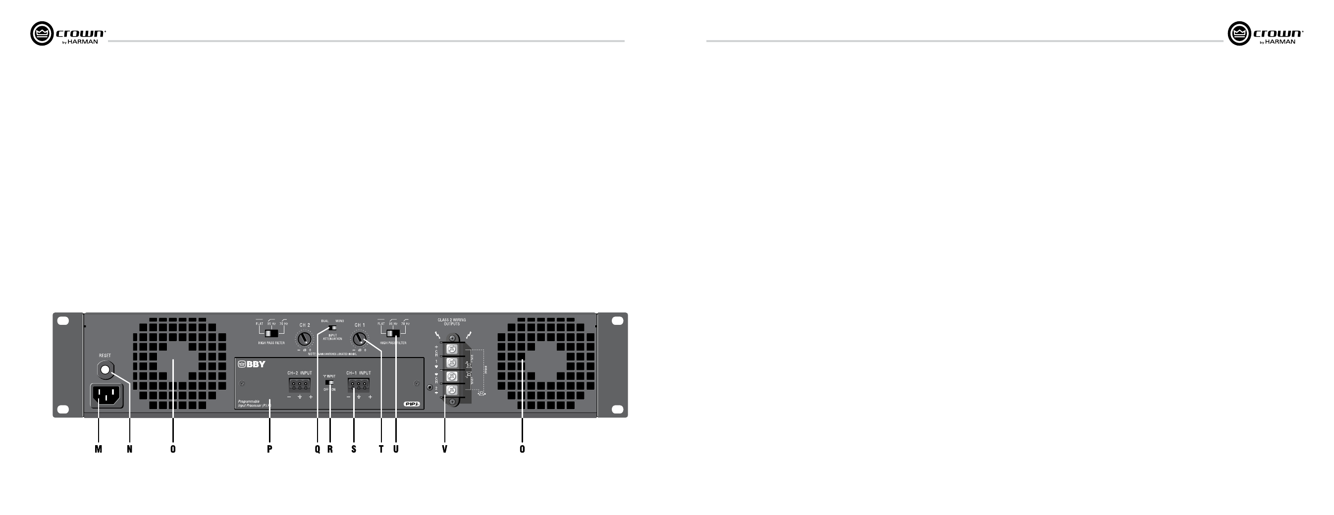
4.3 Back Panel Controls
and Connectors.
cTs 2000/3000 back panel is shown.
cTs 600/1200 look slightly different near
the Reset button.
M. Power cord connector
Standard 15 amp IEC inlet. A circuit breaker
located near the IEC power inlet protects the
amplifier from excessive AC current draw.
N. Reset Switch
Resets the circuit breaker that protects the
power supply.
O. Ventilation grille
Air flow is front to back. Do not block the
ventilation grilles.
P. PiP ™ Input Panel
PIP2-BBY module includes two balanced
3-pin removable barrier connectors. The
“Y” Input Switch is described under
letter R.
Sensitivity Switches
Behind the input panel are the Input
Sensi tivity Switches. One 3-position
switch per channel selects various
sensitivity set tings. See Section 5.2.4 for
details and diagram.
Q. Mode Switch
This two-position switch is used to select
the amplifier’s mode of operation: Dual or
Bridge Mono.
Dual mode is used for 2/4/8 ohms, for 70V
operation with the CTs 600/1200, and for
70/100V operation with the CTs
2000/3000.
Bridge mode is used for 4/8/16 ohms, for
140V operation with the CTs 600/1200,
and for 100/140/200V operation with the
CTs 2000/3000.
R. “Y” input Switch
When set to ON, this switch parallels the
input signals of the two channels, for use
when the input signal is mono. The
ampli fier’s channel outputs are still
independent. The “Y” Input Switch also can
be used to daisy-chain the signal to
another amplifier. See Section 3.6.5 for
details.
S. input connectors
Balanced 3-pin terminal block connectors,
one per channel.
T. channel Level controls
One 21-position detented rotary attenuator
per channel, ranging from –100 dB to 0 dB
gain.
U. High-Pass Filter
One 3-position switch per channel selects
between OFF, 35Hz and 70Hz 3rd-order
fil ters.
V. Speaker connectors
One four-pole touch-proof terminal strip.
Accepts up to 10 AWG terminal forks.
Output cover (not shown)
This covers the output connectors,
pro tecting users from the connectors’
poten tially high voltage. This cover is
required for Class 2 wiring installations.
See Sec tion 3.5 for details on removing
covers that have two holes.
4 Operation
Figure 4.2 CTs 2000 and 3000 Back Panel Controls and Connectors
NOTe: For detailed information about
these crown amplifier features, please
consult the crown Amplifier Application
Guide, available on the crown website
at www.crownaudio.com
5.1 Protection Systems
Your Crown amplifier provides extensive
pro tection and diagnostic capabilities,
including thermal level control, fault indicators,
high-pass filtering, DC protect, AC under/over
volt age protection, inrush limiting, and
variable-speed fans.
5.1.1 Thermal Level Control (TLC)
If the amplifier becomes too hot for safe
opera tion, the light will shine brightly and TLC
will engage the input compressor. By
compressing the input, the amplifier will not
generate as much heat and will have a chance to
cool down. The degree of compression is
proportional to the amount of overheating. This
feature allows the show to go on, rather than
having the amplifier shut down.
5.1.2 Junction Temperature
Simu lation (JTS) (CTs 600/1200
only)
JTS circuitry simulates the operation of the
amplifier’s output transistors, and compares it
against the transistors known Safe Operation
Area (SOA). If JTS sees that more power is
about to be asked of the output devices than
they are capable of delivering under the present
conditions, JTS immediately limits the drive
level until it falls within the SOA. Limiting is
proportional and kept to an absolute minimum-
only what is required to prevent the possibility
of output transistor damage.
This level of protection enables Crown to
increase output transistor utilization while also
greatly increasing amplifier reliability.
5.1.3 Fault
The amplifier will light the Fault LED if the
amplifier output stage stops operating. If this
happens, see Section 8 for servicing
informa tion.
5.1.4 High-Pass Filters
Very low frequency signals contain no useful
musical energy, waste valuable amplifier power
and headroom, and can be damaging to your
speakers. Your Crown amplifier provides high-
pass filters to remove these signals from each
channel’s output.
On the back panel are two 3-position 3rd-order
high-pass filter switches (one per channel) with
selections of Off, 35Hz and 70 Hz.
5.1.5 Low-Pass Filters
Gaussian-approximation ultrasonic filters
pre vent ultrasonic feedback and HF burnout in
drivers. This type of filter preserves transient
response better than a Butterworth filter.
5.1.6 AC Under/Over Voltage
Protection
If the AC line voltage drops below 25% or rises
above 15% of the nominal operating voltage of
the amplifier, the amplifier’s power supply turns
off and the blue Power LED flashes. The
ampli fier will turn back on when the AC line
voltage returns to safe operating levels (within
+15% / -25%).
5.1.7 Circuit Breaker
A circuit breaker located near the IEC power
inlet protects the amplifier from excessive AC
current draw.
5.1.8 DC Output Servo
The output servo circuit protects your drivers by
eliminating DC offset, even in the presence of
very large asymmetrical signals.
5.1.9 Inrush Limiting
A soft-start circuit in the power supply
mini mizes the amplifier’s current draw during
power-on.
5.1.10 Variable-speed Fans
Two continuously variable speed fans direct the
airflow through the amplifier for cooling.
5.2 Advanced Features
5.2.1 Switching Power Supply
Crown’s Switching Power Supply minimizes the
amplifier’s weight.
Typical non-switching power supplies require
large, heavy transformers in order to produce
the required power at the output stage. These
transformers must be large to operate at 50 to
60 Hz (standard AC supplied by the power
company).
By contrast, switching power supplies can
operate with a much smaller (and lighter)
trans former because they first convert the AC up
to a much higher frequency, thereby reducing
waste.
The power supply is voltage-specific, allowing
use in regions using 120V or 240V.
5.2.2 Input Compressor
Prevent input/output overload.
5.2.3 Sleep Circuit
Lowers standby power consumption by shut ting
down the high-voltage supplies during idle
periods.
NOTE: By default, the sleep circuit is not active
on the CTs 600/1200, but may be activated as a
service option.
5 Advanced Features
and Options