4 operation, 3 setup – Crown Audio CTs Series (2 Channel) User Manual
Page 7
Operation Manual
CTs Power Amplifiers
page 12
page 13
CTs Power Amplifiers
Operation Manual
3.7 Connect to AC Mains
On the back panel, check whether your amplifier is labeled
for 120V or 220-240V AC mains. Connect your amplifier to
the corresponding AC mains power source (power out let)
with the supplied AC power cordset. First, connect the IEC
end of the cordset to the IEC connector on the ampli fier.
Then, with the amplifier in the OFF position, plug the other
end of the cordset into the AC mains.
WaRNiNg: The third prong of this connector
(ground) is an important safety feature. do not
attempt to disable this ground connection by
using an adapter or other methods.
Amplifiers don’t create energy. The AC mains voltage and
current must be sufficient to deliver the power you expect.
Check the amplifier’s back-panel label which specifies the
required AC mains voltage and frequency. The AC mains
voltage must be no more than 15% above the required
voltage, and no less than 25% below the required voltage.
The AC mains frequency must be within the required
fre quency range. If you are unsure of the output voltage of
your AC mains, please consult your electrician.
3.8 Startup Procedure
Use the following procedure when first turning on your
amplifier:
1. Turn down the level of your audio source.
2. Turn down the level controls of the amplifier.
3. Turn on the “Power” switch. The Power indicator
should glow. Wait for the “Ready” LED to illuminate.
4. Turn up the level of your audio source to an optimum
level.
5. Turn up the Level controls on the amplifier until the
desired loudness or power level is achieved. Verify
that the Signal LED is flashing.
6. Turn down the level of your audio source to its normal
range.
If you ever need to make any wiring or installation changes,
don’t forget to turn off the amplifier and discon nect the
power cord.
For help with determining your system’s optimum gain
structure (signal levels) please refer to the Crown Ampli fier
Application Guide, available online at
www.crownaudio.com.
4 Operation
4.1 Precautions
Your amplifier is protected from internal and external
faults, but you should still take the following precautions
for optimum performance and safety:
1. Before use, your amplifier first must be configured for
proper operation, including input and output wiring
hookup. Improper wiring can result in serious
operat ing difficulties. For information on wiring and
config uration, please consult the Setup section of this
manual or, for advanced setup techniques, consult
Crown’s Amplifier Application Guide available online
at www.crownaudio.com.
2. Use care when making connections, selecting signal
sources and controlling the output level. The load you
save may be your own!
3. Do not short the ground lead of an output cable to the
input signal ground. This may form a ground loop and
cause oscillations.
4. Never connect the output to a power supply,
battery or power main. electrical shock may
result.
5. Tampering with the circuitry, or making unauthorized
circuit changes may be hazardous and invalidates all
agency listings.
6. Do not operate the amplifier with the red Clip LEDs
constantly flashing.
7. Do not overdrive the mixer, which will cause clipped
signal to be sent to the amplifier. Such signals will be
reproduced with extreme accuracy, and loudspeaker
damage may result.
8. Do not operate the amplifier with less than the rated
load impedance. Due to the amplifier’s output
protec tion, such a configuration may result in
premature clipping and speaker damage.
Remember: Crown is not liable for damage that results
from overdriving other system components.
3 Setup
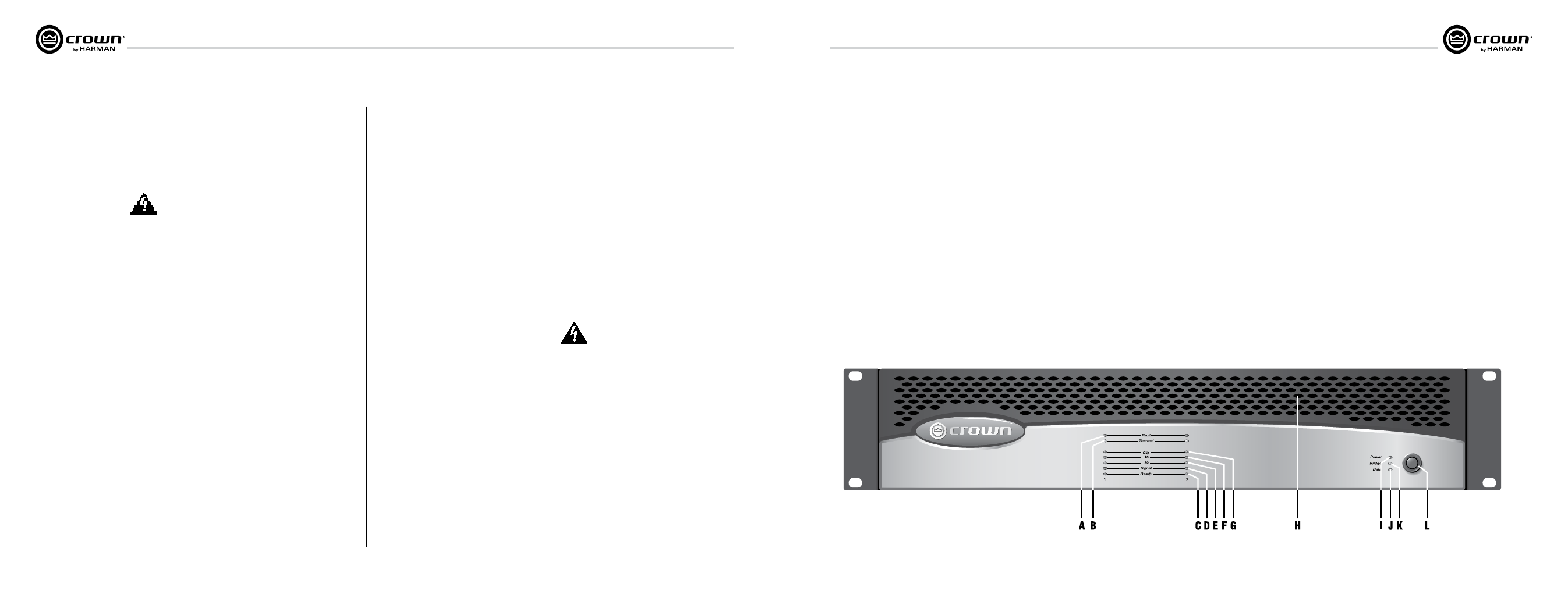
4.2 Front Panel Controls
and Indicators
a. Fault indicator
Red LED, one per channel, flashes when
the amplifier output channel has stopped
operating. Usually this means that the
amplifier must be serviced.
B. Thermal indicator
Red LED, one per channel, illuminates
when the channel has shut down, or is very
near shutting down, due to thermal stress
or overload.
c. Ready indicator
Green LED, one per channel, illuminates
when the channel is initialized and ready to
produce audio output. Indicator is off when
the channel is set to standby mode via the
System Architect or IQ Control Software
packages.
Signal indicators
Three green LEDS per channel indicate the
amplifier’s input and output signal levels.
From bottom to top the LEDs are:
d. Signal: input signal is above –40 dBu.
e. –20 dB: amplifier output is within 20 dB of
clipping.
F. –10 dB: amplifier output is within 10 dB of
clipping.
g. clip indicator
Red LED, one per channel, illuminates
when the channel’s output signal reaches
the onset of audible clipping. The Clip
Indicator also will illuminate during
Ther mal Level Control (TLC) limiting or
when the input compressor/limiter is
protecting the amplifier from input
overload.
H. cooling Vents
Front-to-rear forced airflow.
i. Power indicator
Blue LED indicates AC power has been
applied and is within the safe operating
range of the power supply. The LED will
flash when the AC line voltage is
approxi mately 15% above or 25% below
the nom inal rated value.
J. data indicator
Yellow LED indicates control activity This
LED is driven by the IQ-PIP2 module via
the PIP2
interface. Note: Data indicator
flashes only when the installed PIP module
is polled for data, or is polled to see
whether it is online.
K. Bridge Mode indicator
Yellow LED illuminates when the rear-
panel Mode Switch is set to the “Bridge”
position
L. Power Switch
Push-on / push-off switch.
Figure 4.1 CTs 600 front panel.
4 Operation