Crown Audio Macro-Tech MA-5000VZ User Manual
Page 25
Page 26
Macro-Tech 5000VZ Power Amplifier
Reference Manual
The high-voltage power supplies are also protected by
internal fuses. With rated loads and output levels, a fuse
should only shut down its channel in the rare instance
of a catastrophic amplifier failure. Other protection sys-
tems like
ODEP keep the amplifier operational under
most other severe conditions. A fuse can also shut
down its channel if an extremely low-impedance load
and high output level result in current draw that ex-
ceeds the fuse rating. Again, this should only be pos-
sible when operating
outside rated conditions, like
when the amplifier is used to drive a 1 ohm load in Ste-
reo mode, or when the amplifier is driven with subsonic
square waves. If a high-voltage power supply fuse
blows, please refer the unit to a qualified technician.
4.4 Controls
The Enable switch is located on the front panel so you
can easily turn the amplifier on and off. If you ever need
to make any wiring or installation changes, don’t forget
to disconnect the power cord first. Please follow these
steps when first turning on your amplifier:
1. Turn down the level of your audio source. For ex-
ample, set your mixer’s master volume to –
∞
.
2. Turn down the Level controls of the amplifier (if
they are not already down).
3. Turn on the Enable switch. The Enable indicator
beside the switch should glow. During the four
second turn-on delay which immediately fol-
lows, the Signal/
IOC indicators will light brightly,
the
ODEP indicators will stay off, and the I
Load
/
I
Limit
indicators usually stay off but may flash
immediately after the switch is turned on. After
the turn-on delay, all lights should indicate nor-
mal operation.
4. After the turn-on delay, turn up the level of your
audio source to the maximum desired level.
5. Turn up the level controls of the amplifier until
the maximum desired sound level is achieved.
DANGER: This amplifier produces enough
power to drive loudspeakers to levels that
can cause permanent hearing damage. Be
careful when setting the maximum level.
6. Turn down the level of your audio source to its
normal range.
Each of the front panel Level controls has 31 detents
for accurately repeatable settings. To prevent tamper-
ing, the Level Control Security Kit is available (see Sec-
tion 8.2). In Bridge-Mono and Parallel-Mono modes, the
Channel 2 level control is bypassed.
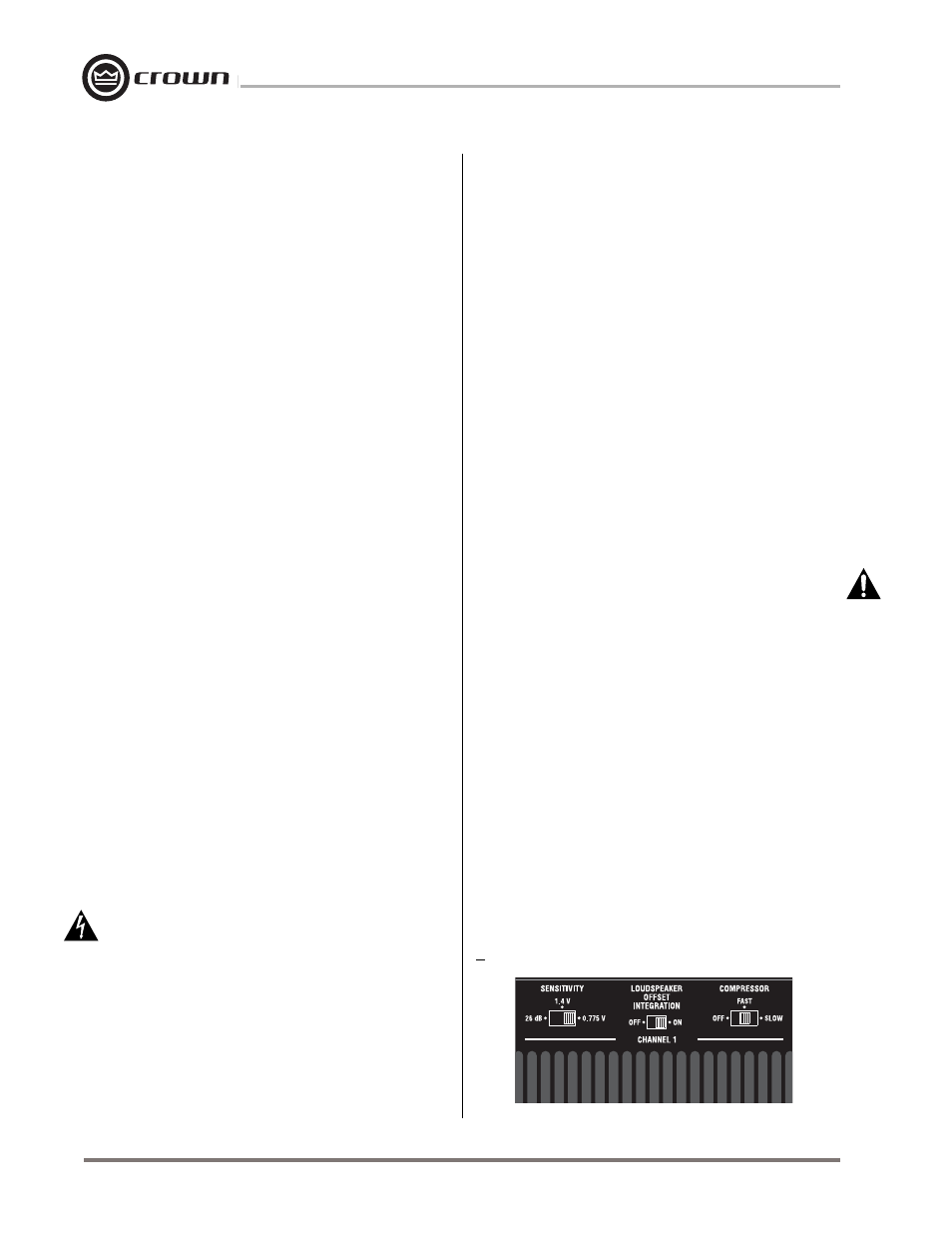
The three-position input sensitivity switches are lo-
cated on the back panel and are factory set to
0.775 volts for standard 1 kHz power. They may be set
to 1.4 volts for standard 1 kHz power, or a voltage gain
of 26 dB. When set to 26 dB gain, the input sensitivity is
5.1 volts for full output.
The Loudspeaker Offset Integration (LOI) switches
are located on the back panel of the amplifier and are
factory set to the “on” position. The LOI circuits use
double integrating filters in the amplifier’s feedback cir-
cuitry to protect loudspeakers in several different ways.
First, they center asymmetrical audio waveforms that
cause off-center woofer cone movement. Off-center
cone movement increases loudspeaker heating and
distortion while reducing the loudspeaker’s power han-
dling ability. Second, LOI filters unwanted DC and sub-
sonic frequencies using a third-order Butterworth filter
with a 35 Hz corner frequency. Third, LOI filters un-
wanted ultrasonic frequencies (RF) that can cause
tweeter burnout using a second-order Bessel filter with
a 50 kHz corner frequency.
IMPORTANT: The Loudspeaker Offset Integration
circuitry does NOT protect loudspeakers from large
transient voltages or excessive power levels for pro-
longed periods of time. Crown cannot be held liable
for damage or personal injury that results from over-
driving loudspeakers or other system components. See
Section 3.3.6 for information on using fuses to protect
loudspeakers.
The compressor switches are located on the back
panel of the amplifier and are factory set to the “fast”
setting. If desired, they can be switched to “slow” or
“off.” Because the compressors are ahead of all other
input circuitry, they compress the input signals before
clipping or other types of distortion can be generated.
Each compressor is driven by the channel’s input over-
load and
IOC error signals. If the IOC circuit senses
that distortion in the output of the amplifier is equal to or
greater than 0.05%, it generates an “error signal” that
causes the
IOC indicator on the front panel to flash
brightly, and the compressor to compress the input sig-
Fig. 4.3 Input Sensitivity, LOI and Compressor Switches