Iq system, Fig. 3.13 loudspeaker fuse nomograph – Crown Audio Macro-Tech MA-5000VZ User Manual
Page 19
Page 20
Macro-Tech 5000VZ Power Amplifier
Reference Manual
7. If the size of the cable exceeds what you want to use,
(1) find a way to use shorter cables, like using an
IQ
System
, (2) settle for a lower damping factor, or (3) use
more than one cable for each line. Options 1 and 2 will
require the substitution of new values for cable length
or damping factor in the nomograph. For option 3, esti-
mate the effective wire gauge by subtracting 3 from the
apparent wire gauge every time the number of con-
ductors of equal gauge is doubled. So, if #10 wire is
too large, two #13 wires or four #16 wires can be used
for the same effect.
SOLVING OUTPUT PROBLEMS
Sometimes high-frequency oscillations occur which
can cause your amplifier to prematurely activate its pro-
tection circuitry and result in inefficient operation. The
effects of this problem are similar to the effects of the
RF problem described in Section 3.3.4. To prevent
high-frequency oscillations:
1. Turn on Loudspeaker Offset Integration for each
channel. It includes a low-pass filter to prevent
RF problems (see Section 3.3.4).
2. Lace together the loudspeaker conductors for
each channel (do not lace together the conduc-
tors from different channels). This minimizes the
chance that cables will act like antennas and
transmit or receive high frequencies that can
cause oscillation.
3. Avoid using shielded loudspeaker cable.
4. Avoid long cable runs where the loudspeaker
cables from different amplifiers share a common
cable tray or cable jacket.
5. Never connect the amplifier’s input and output
grounds together.
6. Keep loudspeaker cables well separated from
input cables.
7. Install the input wiring according to the instruc-
tions in Section 3.3.4.
Another problem to avoid is the presence of large in-
frasonic currents when primarily inductive loads are
used. Such loads include 70 volt step-up transformers
and electrostatic loudspeakers.
Inductive loads may appear as a short circuit at low
frequencies. This can cause the amplifier to produce
large low-frequency currents and activate its protec-
tion circuitry. Always turn on the LOI circuitry when a
primarily inductive load is used. The LOI circuitry pro-
vides protection from most low-frequency input and
output problems.
3.3.6 Additional Load Protection
Your amplifier can generate high power levels. If your
loudspeakers do not have built-in protection from ex-
cessive power, it’s a good idea to protect them. Loud-
speakers are subject to thermal damage from
sustained overpowering and mechanical damage from
large transient voltages. Special fuses can be used to
protect your loudspeakers in both cases.
Different types of fuses are required for thermal protec-
tion and voltage protection. Slow-blow fuses are usu-
ally selected to protect loudspeakers from thermal
damage because they are similar to loudspeakers in
the way they respond to thermal conditions over time.
In contrast, high-speed instrument fuses like the
Littlefuse 361000 series are used to protect loudspeak-
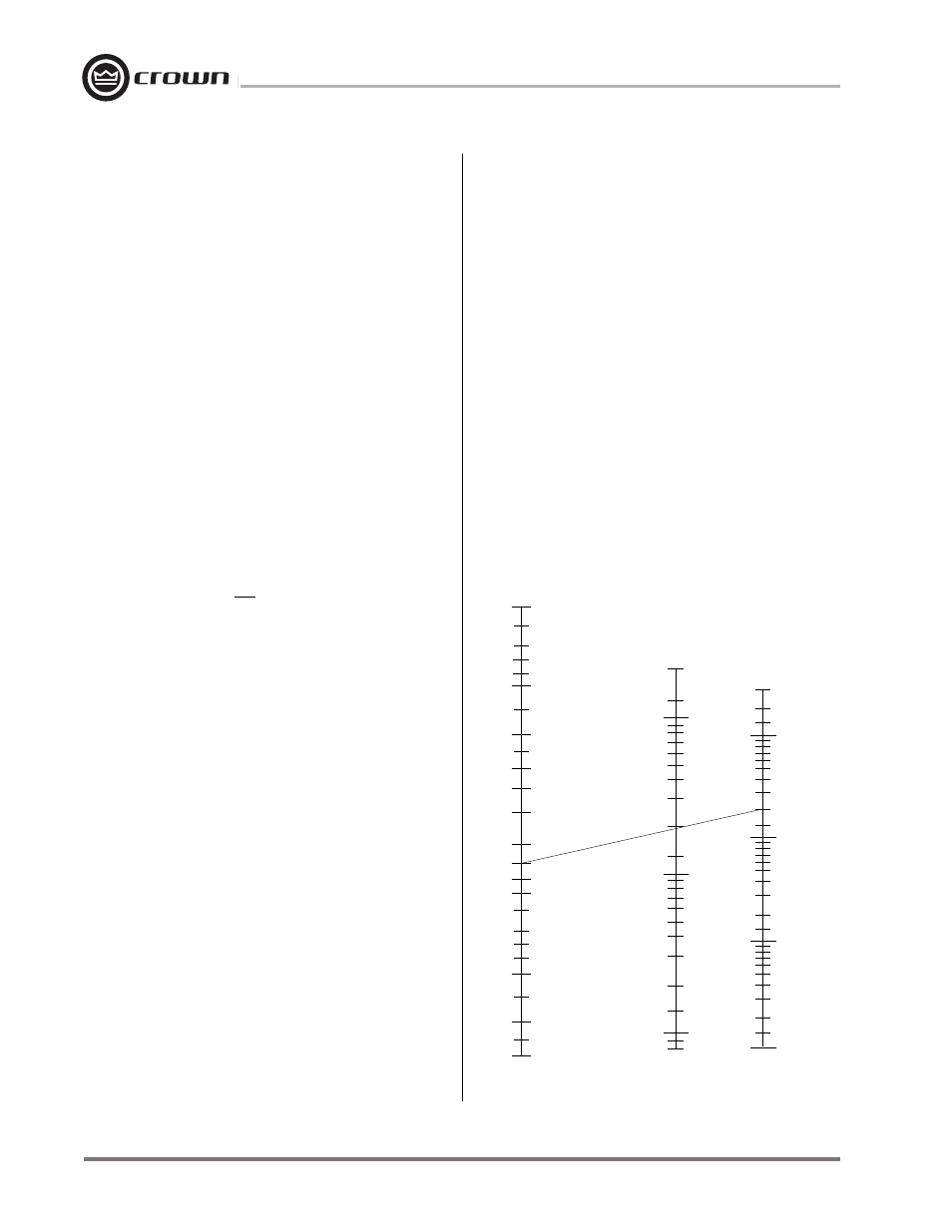
ers from large transient voltages. The nomograph in
Figure 3.13 can be used to select the properly rated
fuse for either type of loudspeaker protection.
There are basically two approaches that can be taken
when installing fuses for loudspeaker protection. A
common approach is to put a single fuse in series with
Fig. 3.13 Loudspeaker Fuse Nomograph
1.0
1.2
1.4
1.6
2.5
3
4
5
6
7
8
9
10
12
14
16
20
25
30
20
15
10
8
6
5
4
3
2
1.5
1
.8
.6
.5
.4
.3
.2
.15
.1
.08
3000
2000
1500
1000
800
600
400
300
200
150
100
80
60
40
30
20
15
10
8
6
4
3
2
1.5
1
SPEAKER IMPEDANCE
(ohms)
FUSE
(amps)
SPEAKER POWER RATING
PEAK MUSIC POWER
(watts)
(Typically 4 times the continuous average power)
Example:
Impedance = 8 ohms.
Peak Power = 200 W
Answer:
Fuse = 2 A
2
40