4 operation, Continued) – Crown Audio Macro-Tech MA5002VZ User Manual
Page 12
Operation Manual
MA-5002VZ Power Amplifier
page 12
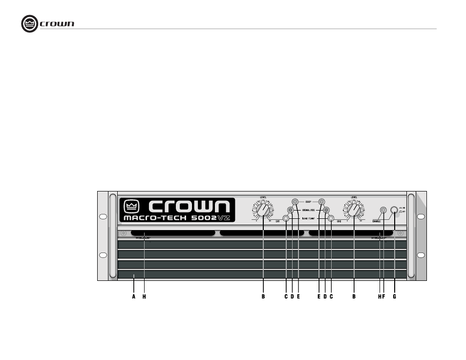
4.2 Front Panel Controls
and Indicators
A. Dust Filter
Removes large particles from the air at the
air intake. The filter elements can be easily
removed for cleaning by gently pulling
them away from the front panel. Filters can
be cleaned by soaking in a mild detergent
and water.
B. Level Control
Rotary detented level control, one per
channel.
C. ILoad/ILimit Indicator
Dual-color LED, one per channel. Indicator
is off when there is no significant load cur-
rent (extremely low or no input signal, or
no load connected to the channel's out-
put); illuminates green to indicate that load
current is flowing; and illuminates red if
the amplifier has reached its maximum
output current capacity. See Section 5.2.3
for more about ILoad/ILimit.
D. Signal/IOC Indicator
Green LED, one per channel. Dual-pur-
pose indicator illuminates to indicate the
presence of input signals; flashes brightly
with a 0.1-second hold delay to indicate a
difference (distortion) between the input
and output signal of 0.05% or greater; and
flashes brightly with a 0.5-second hold
delay to indicate input clipping distortion.
See Section 5.1.2 for more about IOC.
E. ODEP Indicator
Amber LED, one per channel, illuminates
brightly to indicate presence of thermody-
namic energy. They dim proportionally as
energy reserves decrease. In the event that
energy reserves are depleted, the indica-
tors turn off and ODEP limiting occurs.
See Section 5.1.1 for more about ODEP.
F. Enable Indicator
Green LED indicates amplifier has been
turned on and AC power is available.
G. Enable Switch
Amplifier is on when the switch is in the IN
position.
H. VZ Mode Switch
Four-position switch, one Per Channel.
Allows selection of “VZ-ODEP,” “Lock
Low,” and “VZ” power supply modes, from
left to right (right-most two positions both
select VZ mode). See Section 5.2.2 for
more about VZ and the VZ Mode Switch.
Figure 4.1 Front Panel
Controls and Indicators
(shown with top filter grille
removed for clarity)
4 Operation
(continued)