3 setup, Continued) – Crown Audio Macro-Tech MA5002VZ User Manual
Page 10
Operation Manual
MA-5002VZ Power Amplifier
page 10
3.6.3 Parallel-Mono Mode
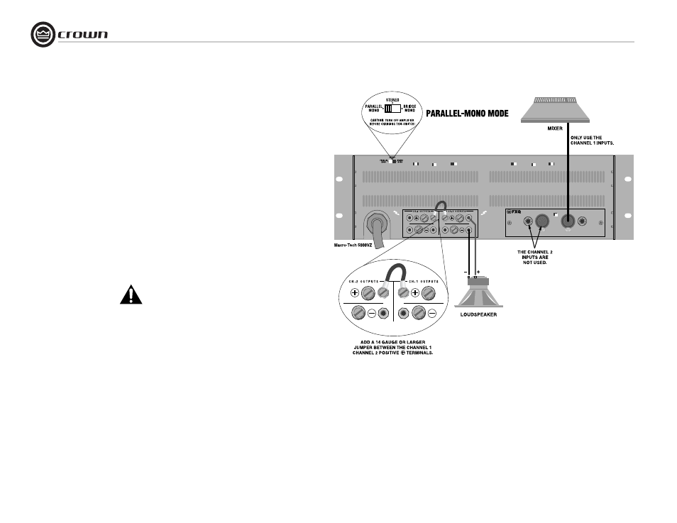
Typical input and output wiring is shown in
Figure 3.8.
INPUTS: Connect input wiring to Channel 1.
Refer to Figure 3.4 for input connector pin
assignments.
OUTPUTS: Install a jumper wire between the
positive outputs of both Channel 1 and Channel
2 that is at least 14 gauge in size; Connect posi-
tive (+) speaker lead to Channel 1 positive
output of amp; connect negative (-) speaker lead
to Channel 2 negative output of amp. Refer to
Section 3.5 for output connector pin assign-
ments. Make sure the Mode switch is set to the
“Parallel” position when operating in Parallel-
Mono mode.
NOTE: Turn down (full CCW) the Channel
2 level control when operating in
Parallel-Mono mode, as the lower-
numbered level control works both
channels.
NOTE: Remove the jumper wire before
changing to any mode except Parallel-
Mono.
NOTE: Crown provides a reference of wiring pin
assignments for commonly used connector
types in the Crown Amplifier Application Guide
available at www.crownaudio.com.
Figure 3.8 System Wiring, Parallel-Mono Mode
3 Setup
(continued)