3B Scientific SW Ultrasonics Set (115 V, 50__60 Hz) User Manual
Page 9
9
7.3
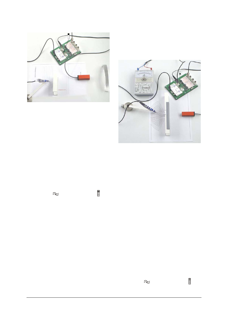
Diffraction by an edge
Fig. 6 Recording isophases when plane waves are
diffracted by an edge
Required:
1 Electronics board and plug-in power supply
1 Ultrasonic transmitter, 40 kHz
1 Ultrasonic pen with holder
1 Convex mirror
1 Reflector
•
Connect the supplied plug-in transformer to
provide power to the equipment.
•
Set up the convex mirror and mark the focal
point (focal length 100 mm).
•
Connect the ultrasonic transmitter to Gen-
erator G1 and set it up facing the convex
mirror at the mirror’s focal point.
•
Turn on the high-pass filter by means of
switch S1 (
) and set switch S2 to in or-
der to couple to Generator G1.
•
Connect the ultrasonic pen to channel A and
set it up in its holder in such a way that the
tip is only about 1 mm from the template.
•
Set up the ultrasonic pen in its holder behind
the transmitter such that it is pointing to-
wards the convex mirror.
•
Move the ultrasonic pen until the phase indi-
cator goes out and then mark the position of
the ultrasonic pen on the template.
•
To record the wave fronts after reflection
from the convex mirror move the ultrasonic
pen across the axis of the beam and mark
the points where the brightness of the phase
indicator is art a minimum.
•
Move the ultrasonic pen in the direction of
the beam and record the following isophase.
•
Set up the reflector such that diffraction oc-
curs at its edge and determine the altered
isophases due to the diffraction.
Note: The isophases (points where the bright-
ness is at a minimum) correspond to a “snap-
shot” of the wave fronts. The distance between
two isophases is equal to one wavelength.
7.4
Diffraction by a double slit
Fig. 7 Diffraction by a double slit
Note: New circular wave fronts emerge from
both slits. The template already has such wave
fronts drawn on it with a separation of half a
wavelength. The points where these lines cross
form lines (hyperbolae) indicating constructive
and destructive interference.
Required:
1 Electronics board and plug-in power supply
1 Ultrasonic transmitter, 40 kHz
1 Ultrasonic pen with holder
1 Set for double slit
1 Absorber
1 BNC/4-mm cable
Additionally required:
1 ESCOLA 10 multimeter
1006810
•
Connect the supplied plug-in transformer to
provide power to the equipment.
•
Use the appropriate template.
•
Set up the double slit, making sure the slits
are the same width (about 5 mm).
•
Connect the 40-kHz ultrasonic transmitter to
Generator G1 and align it with the middle of
the double slit.
•
Turn on the high-pass filter by means of
switch S1 (
) and set switch S2 to in or-
der to couple to Generator G1.