3B Scientific SW Ultrasonics Set (115 V, 50__60 Hz) User Manual
Page 6
6
6. Operation
6.1
Ultrasonics experiments at 40.000 kHz
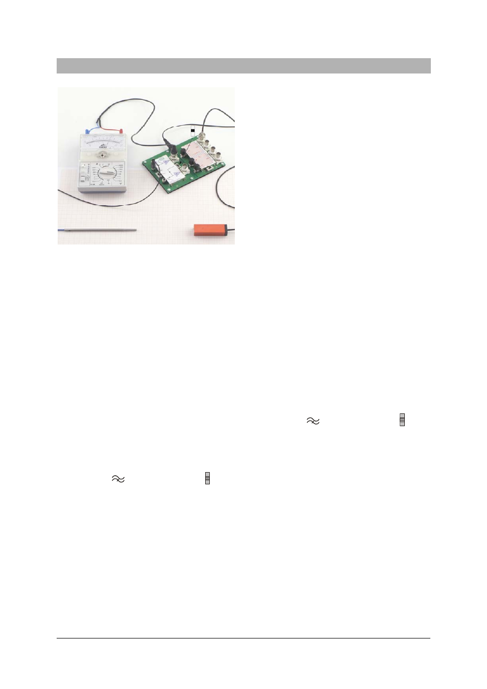
Fig. 2 Measurement of ultrasonic amplitude using a
multimeter
Required:
1 Electronics board with plug-in power supply
1 Ultrasonic transmitter, 40 kHz
1 Microphone probe
or
1 Ultrasonic pen
1 BNC cable
or
1 BNC/4-mm cable
Additionally required:
1 USB oscilloscope, 2x40 MHz
1012845
or
1 Analog oscilloscope, 2x20 MHz
1008695
or
1 ESCOLA 10 multimeter
1006810
•
Connect the supplied plug-in transformer to
provide power to the equipment.
•
Turn on the high-pass filter by means of
switch S1 (
) and set switch S2 to .
•
Connect the 40-kHz ultrasonic transmitter to
the output of Generator G1.
•
Place the microphone probe opposite the
transmitter and connect it to channel A or B
on the electronics board.
Note: The ultrasonic pen can be used in-
stead of the microphone probe and con-
nected to channel A or B. Its tip should point
towards the sound source.
•
Connect the output of the channel to an
oscilloscope (measuring ranges 1 V/div, 2
µs/div) or a multimeter (measuring range:
AC, 10 V).
•
Observe the amplitudes of the oscillations
with the oscilloscope or via the deflection of
the multimeter and vary the amplitude of the
ultrasound from the transmitter using the
amplitude trimmer.
Note: the deflection of the multimeter needle
is initially proportional to the set amplitude.
At higher amplitudes the amplifier becomes
overdriven and the output voltage takes on a
square-wave character, since the voltage
level at Output A merely switches between
the negative and positive operating voltages
of the electronics board. The oscilloscope
displays a trapezoidal or square curve.
6.2 Ultrasonic
experiments
with
variable
frequencies
Required:
1 Electronics board and plug-in power supply
1 Ultrasonic transmitter, 40 kHz
1 Microphone probe
or
1 Ultrasonic pen
1 BNC cable
Additionally required:
1 USB oscilloscope, 2x40 MHz
1012845
or
1 Analog oscilloscope, 2x20 MHz
1008695
•
Connect the supplied plug-in transformer to
provide power to the equipment.
•
Turn on the high-pass filter by means of
switch S1 (
) and set switch S2 to .
•
Connect the 40-kHz ultrasonic transmitter to
the output of Generator G2.
•
Place the microphone probe opposite the
transmitter and connect it to channel A or B
on the electronics board.
Note: The ultrasonic pen can be used in-
stead of the microphone probe and con-
nected to channel A or B. Its tip should point
towards the sound source.
•
Connect the output of the channel to an
oscilloscope (measuring ranges 1 V/div, 2
µs/div).
•
Observe the amplitudes of the oscillations
with the oscilloscope and vary the amplitude
of the ultrasound from the transmitter using
the amplitude trimmer.
•
Observe the period of oscillation with the
oscilloscope and vary the frequency of the
transmitter using the frequency trimmer.