3B Scientific SW Ultrasonics Set (115 V, 50__60 Hz) User Manual
Page 3
3
5. Components
5.1 Electronics
board
12V AC
Δϕ
AB
G
2
f
40 kHz
25 kHz
A
B
11
12
9
10
13
1
3
5
8
6
7
2
4
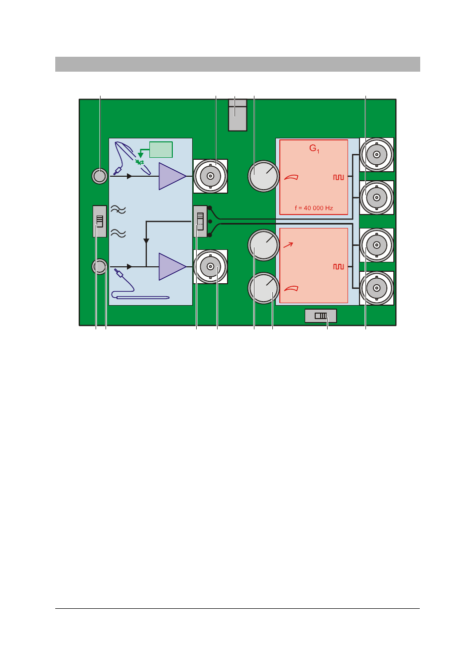
Fig. 1 Electronics board
1 Switch
S1
2 Input for channel B
3 Switch
S2
4 Output for channel B
5 Frequency trimmer for generator G2
6 Amplitude trimmer for generator G2
7 Switch
S3
8 Outputs for generator G2
9 Outputs for generator G1
10 Amplitude trimmer for generator G1
11 Co-axial connector for plug-in power supply
12 Output for channel A
13 Input for channel A
The electronics board for operating the equip-
ment provides the power feed for the ultrasonic
transmitter and amplification for signals from the
microphone probes or ultrasonic pen, as well as
handling control of the phase indicator in the
ultrasonic pen.
The electronics board consists of a generator
block in two parts and a two-channel amplifier
block, which also includes a functional unit for
comparing phase between the two channels.
The AC voltages for the ultrasonic transmitter
are produced in the generator block. Generator
G1 is stabilised to 40.000 kHz by a quartz oscil-
lator, while G2 can be switched between fre-
quencies of 25 and 40 kHz, which can also be
varied by about ±0.5%. Both generators are
equipped with an amplitude trimmer and two
output sockets connected in parallel.
In the amplifier block, the voltages from the ul-
trasonic probes are amplified and output to the
BNC sockets. It is possible to connect a high-
pass filter into the circuit for both channels, in
order to filter out low-frequency components of
the sound.
After the input amplifiers there is a functional
block which compares the signals from channels