3B Scientific SW Ultrasonics Set (115 V, 50__60 Hz) User Manual
Page 7
7
6.3
Investigation of phase differences us-
ing the phase indicator on the ultra-
sonic pen
Required:
1 Electronics board and plug-in power supply
1 Ultrasonic transmitter, 40 kHz
1 Ultrasonic pen
2 BNC cables
Additionally required:
1 USB oscilloscope, 2x40 MHz
1012845
or
1 Analog oscilloscope, 2x20 MHz
1008695
•
Connect the supplied plug-in transformer to
provide power to the equipment.
•
Connect the ultrasonic transmitter to Gen-
erator G1 or alternatively to Generator G2.
•
Connect the ultrasonic pen to channel A.
•
Turn on the high-pass filter by means of
switch S1 (
) and either set switch S2 to
in order to couple to Generator G1 or in
order to couple to Generator G2.
•
Connect the channel outputs to the oscillo-
scope..
•
Move the ultrasonic pen to a position where
the LED acting as a phase indicator is lit to
its maximum intensity and compare the
phase differences between the two signals.
Note: the phase indicator shows the differ-
ence between the generator signal and the
signal received from the ultrasonic pen.
The phase relationship between two arbi-
trary points on the ultrasonic wave are ana-
lysed when a microphone probe is con-
nected to channel A and switch S2 is set to
.
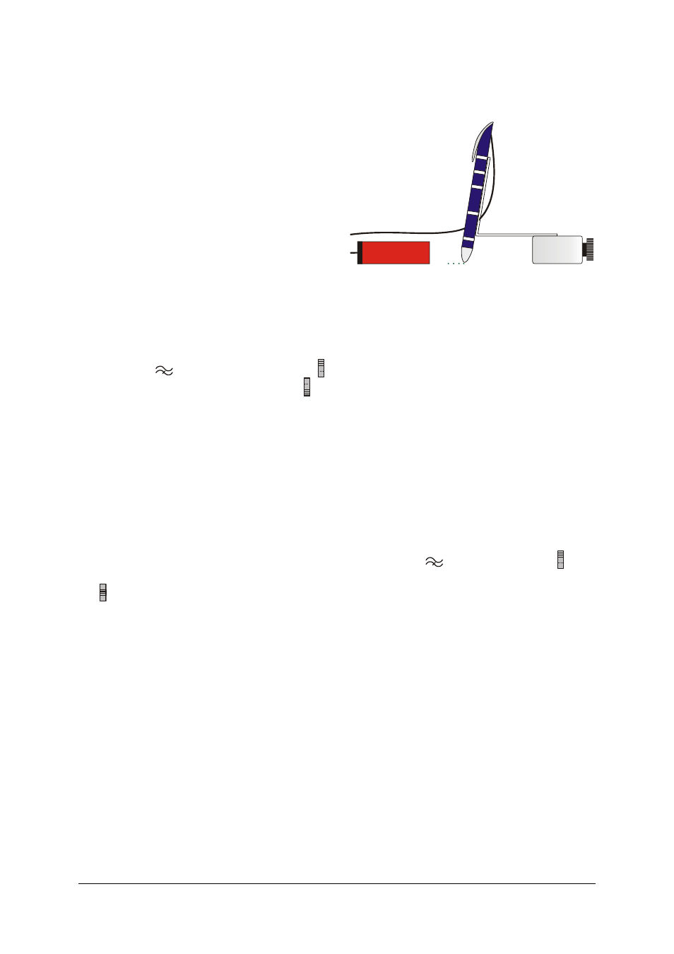
6.4
Recording of isophases or determina-
tion of wavelength with the ultrasonic
pen
Fig. 3 Positioning of ultrasonic pen on work base and
alignment towards sound source
Required:
1 Electronics board and plug-in power supply
1 Ultrasonic transmitter, 40 kHz
1 Ultrasonic pen
1 Holder for ultrasonic pen
•
Use a plain sheet of paper as a base.
•
Connect the supplied plug-in transformer to
provide power to the equipment.
•
Connect the ultrasonic transmitter to Gen-
erator G, for example.
•
Connect the ultrasonic pen to channel A and
set it up in its holder in such a way that the
tip is only about 1 mm from the paper with
the holder pointing towards the sound
source.
•
Turn on the high-pass filter by means of
switch S1 (
) and set switch S2 to in or-
der to couple to Generator G1.
•
Move the ultrasonic pen to a position where
the LED is only lit to its minimum intensity.
•
Use a fine pen to mark the position of the
ultrasonic pen’s tip on the paper.
To record isophases:
•
Move the ultrasonic pen across the line of
the beam until the phase indicator is once
again at its minimum, making sure you keep
the pen pointing towards the transmitter.
•
Use a fine pen to mark the new position of
the ultrasonic pen on the paper.
To determine wavelength:
•
Move the ultrasonic pen in the direction of
the beam until the phase indicator is once
again at a minimum.
•
Use a fine pen to mark the new position of
the ultrasonic pen on the paper.